

Safe and Secure Door Plate
- Summary
- Abstract
- Description
- Claims
- Application Information
AI Technical Summary
Benefits of technology
Problems solved by technology
Method used
Image

Examples
Embodiment Construction
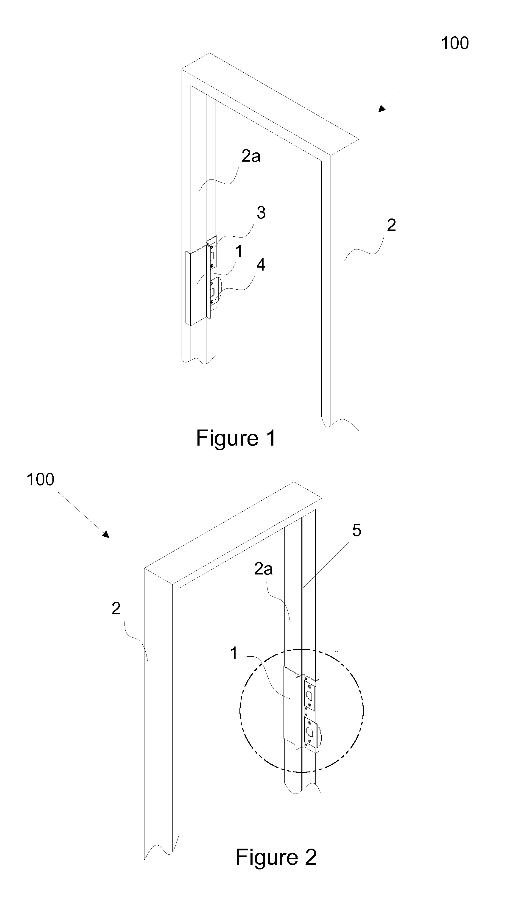
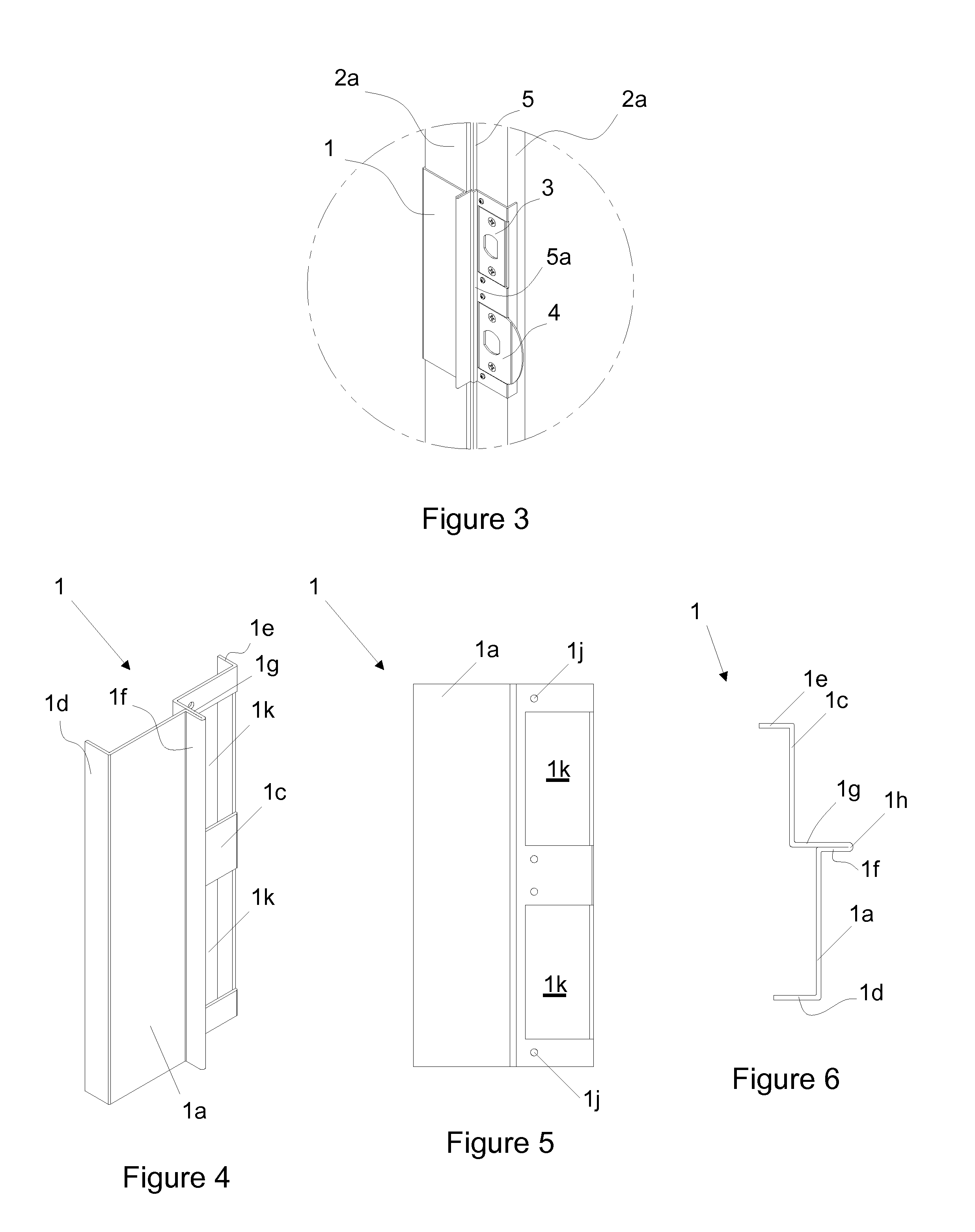
[0025]FIG. 1 shows a jamb and safety plate assembly 100. The assembly comprises an ordinary doorjamb 2 including a step 2a. FIG. 1 shows the assembly 100 without any exterior brick molding or the interior trim casing. FIGS. 1 and 2 show a safety plate 1 fixed to the doorjamb 2 and two strike plates 3, 4 of a lock unit and deadbolt unit not shown. Adjacent to the step 2a, a weather strip 5 runs along the boarder of the doorjamb and a portion of a weather strip 5a is affixed to over the safety plate 1 as shown in FIGS. 2 and 3.
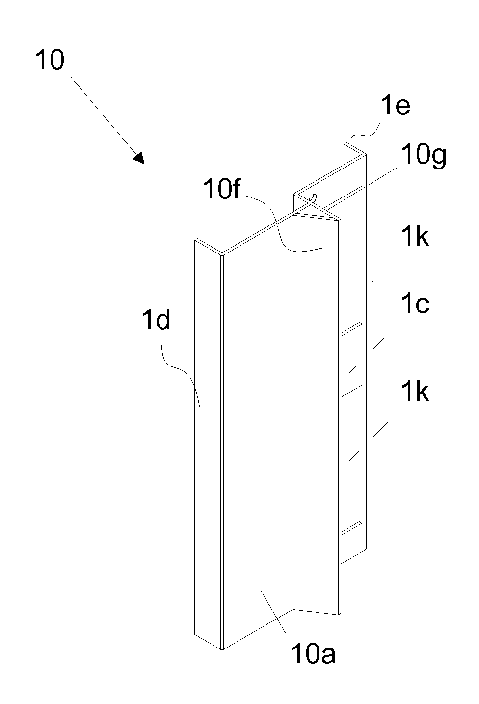
[0026]FIGS. 4-6 show the details of the safety plate 1. The safety plate 1 is comprised of a first web 1a and a second web 1c with a reinforcement hem 1h shown in FIG. 6. The first web 1a and the second web 1c are offset and parallel to each other. The reinforcement hem 1h is comprised of a first lip 1f extending perpendicular to the first flange 1a and bending to a second lip 1g that perpendicularly intersects the second web 1c. As shown in FIG. 5, the second w...
PUM
 Abstract
Description
Claims
Application Information