Developer discharge auxiliary tool and method for discharging developer

Active Publication Date: 2014-12-04
KONICA MINOLTA INC
View PDF2 Cites 2 Cited by
  • Summary
  • Abstract
  • Description
  • Claims
  • Application Information

AI Technical Summary

Benefits of technology

The present invention aims to provide a tool and method for discharging developer to decrease the burden on the development unit. The technical effect is to simplify the process of discharging developer.

Problems solved by technology

At that time, the discharge work needs to be performed while maintaining the developing unit at a certain height from the work table so that the discharged developer does not adhere to the developing unit since the developing unit and the image forming apparatus in which the developing unit is set can be damaged if the discharged developer adheres to the developing unit.
Since the developing unit has a considerable weight due to its various components such as a stirring screw for stirring and carrying the developer in the developing unit and a developing roller, it is a great burden to discharge the developer while holding the developing unit.

Method used


Image

  • Developer discharge auxiliary tool and method for discharging developer
  • Developer discharge auxiliary tool and method for discharging developer
  • Developer discharge auxiliary tool and method for discharging developer

Examples


Embodiment Construction

[0033]Hereinafter, a developer containing box according to an embodiment of the present invention will be explained with reference to the drawings. However, the scope of the invention is not limited to the illustrated examples. In the description below, same reference numerals are provided to the units which have the same functions and configurations, and the explanation thereof is omitted.

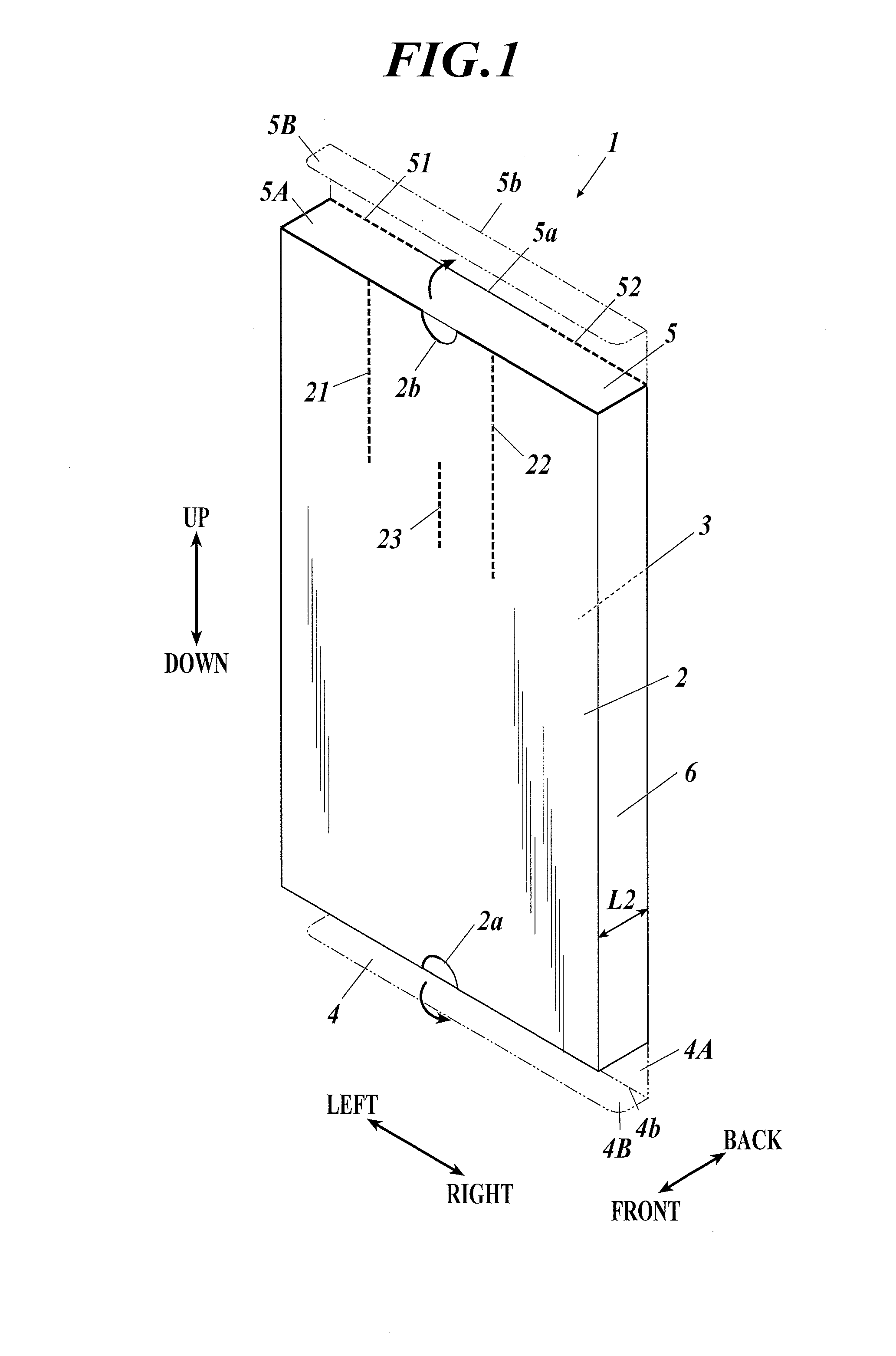
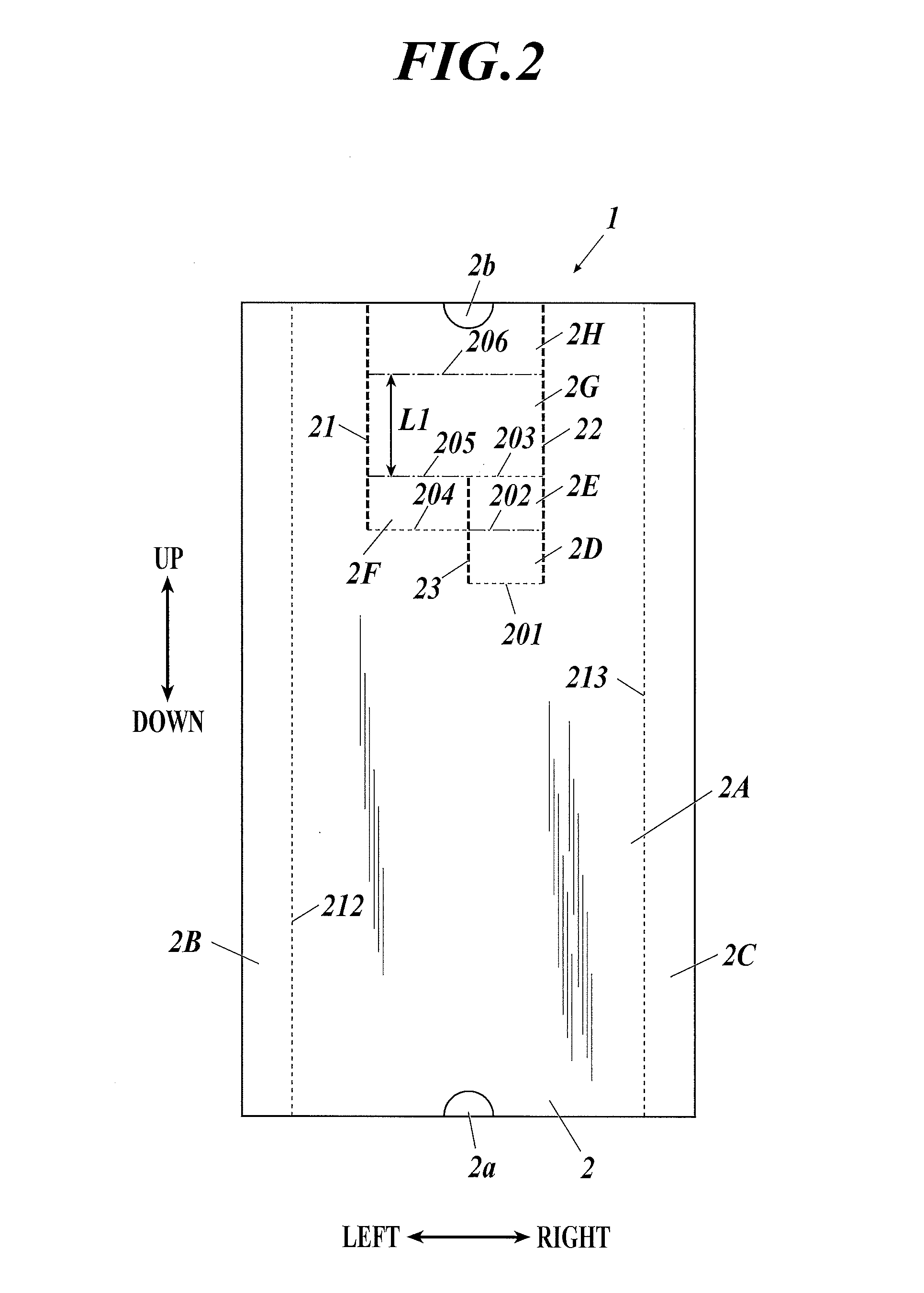
[0034]The configuration of the developer containing box 1 according to the embodiment will be described with reference to FIGS. 1 to 3.

[0035]The developer containing box 1 according to the embodiment is a box which contains developer to be filled in a developing unit that is to be attached to an electrophotographic image forming apparatus, for example. The developer containing box 1 is formed of cardboard, for example. The material of the developer containing box 1 is not limited to cardboard, and various materials such as resin and metal can be applied; however, it is preferable that the develope...


PUM


Abstract

A developer discharge auxiliary tool, including a supporting section which supports a developing unit, that is provided with a discharge port to discharge developer contained therein, at a predetermined height with the discharge port down in a state in which the discharge port is located on a lateral or lower side of the developing unit.

Description

BACKGROUND OF THE INVENTION[0001]1. Field of the Invention[0002]The present invention relates to an auxiliary tool for discharging developer and a method for discharging the developer.[0003]2. Description of Related Art[0004]In electrophotographic image forming apparatuses, toner images are formed by holding toners with developing rollers in developing units which contain developers (developing agents) including toners, making the toners approach electrostatic latent images formed on image holding bodies such as photoreceptors and absorbing the toners to the electrostatic latent images by electrostatic forces.[0005]As described in Japanese Patent Application Laid Open Publication No. 2010-224210, for example, a developing unit is provided with a discharge port for discharging a developer at one end in its longer direction, and thus, the developing unit can be reused by being refilled with a new developer after discharging, through the discharge port, the developer in which the toner...

Claims


Application Information

Patent Timeline
IPC IPC(8): G03G15/00
CPCG03G21/1676G03G15/0893
Inventor SAKURADA, TAKUMI
Owner KONICA MINOLTA INC
Why Eureka
Try Eureka