
Communication device and communication method

Inactive Publication Date: 2005-04-12
LENOVO INNOVATIONS LTD HONG KONG
View PDF18 Cites 7 Cited by
  • Summary
  • Abstract
  • Description
  • Claims
  • Application Information

AI Technical Summary

Benefits of technology

An objective of the present invention is to provide a communication device and a communication method, each which can decrease the burden on a network and can acquire predetermined information quickly and smoothly.

Problems solved by technology

As a result, the terminal may not be connected to the server for a fixed period.
This approach increases error data, partial data missing, and an increased frequency of re-transmission on the network so that data cannot be stably transmitted and received on the network.

Method used


Image

  • Communication device and communication method
  • Communication device and communication method
  • Communication device and communication method

Examples


first embodiment

(First Embodiment)

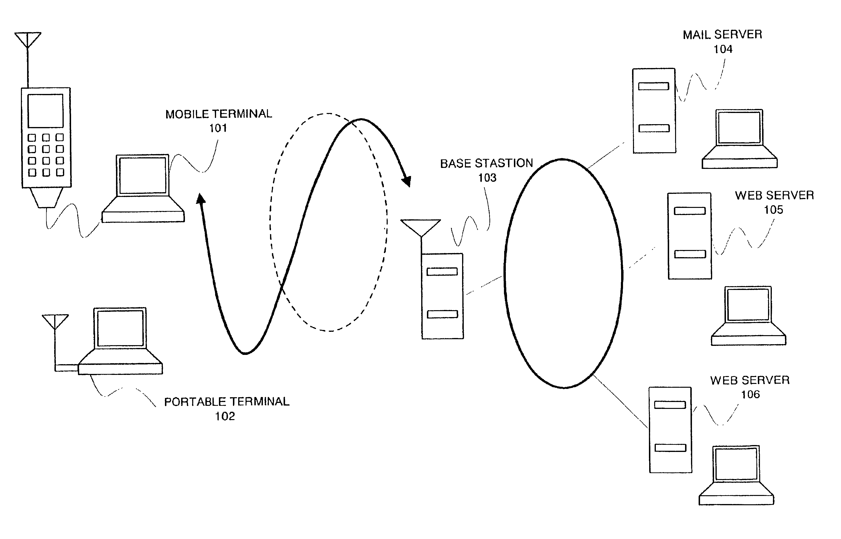
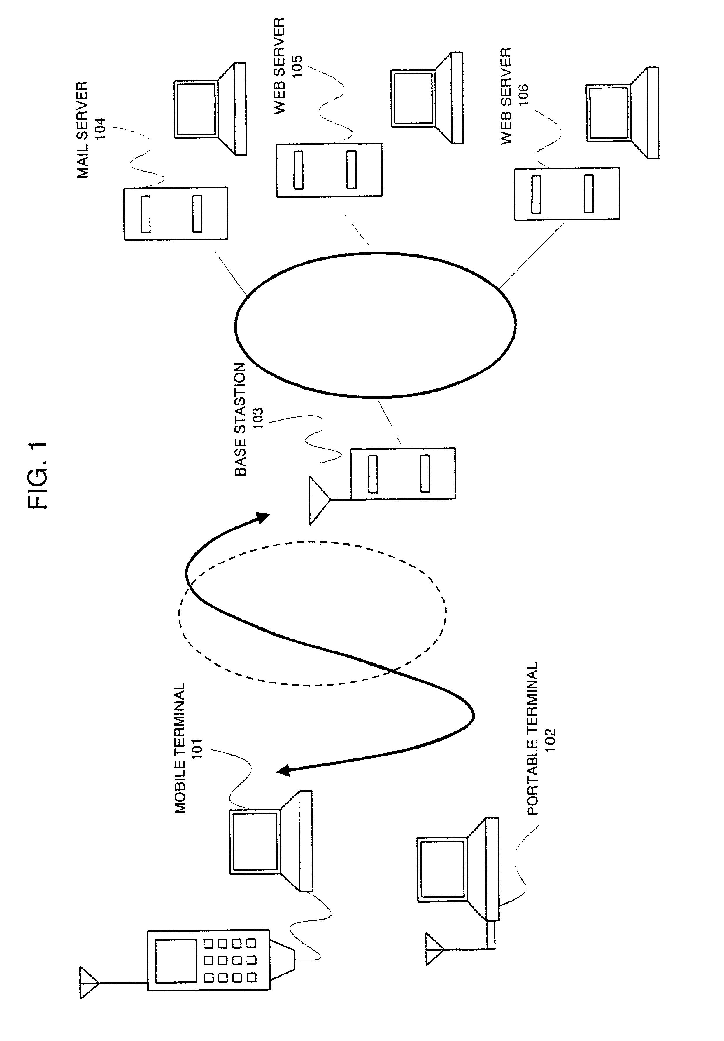
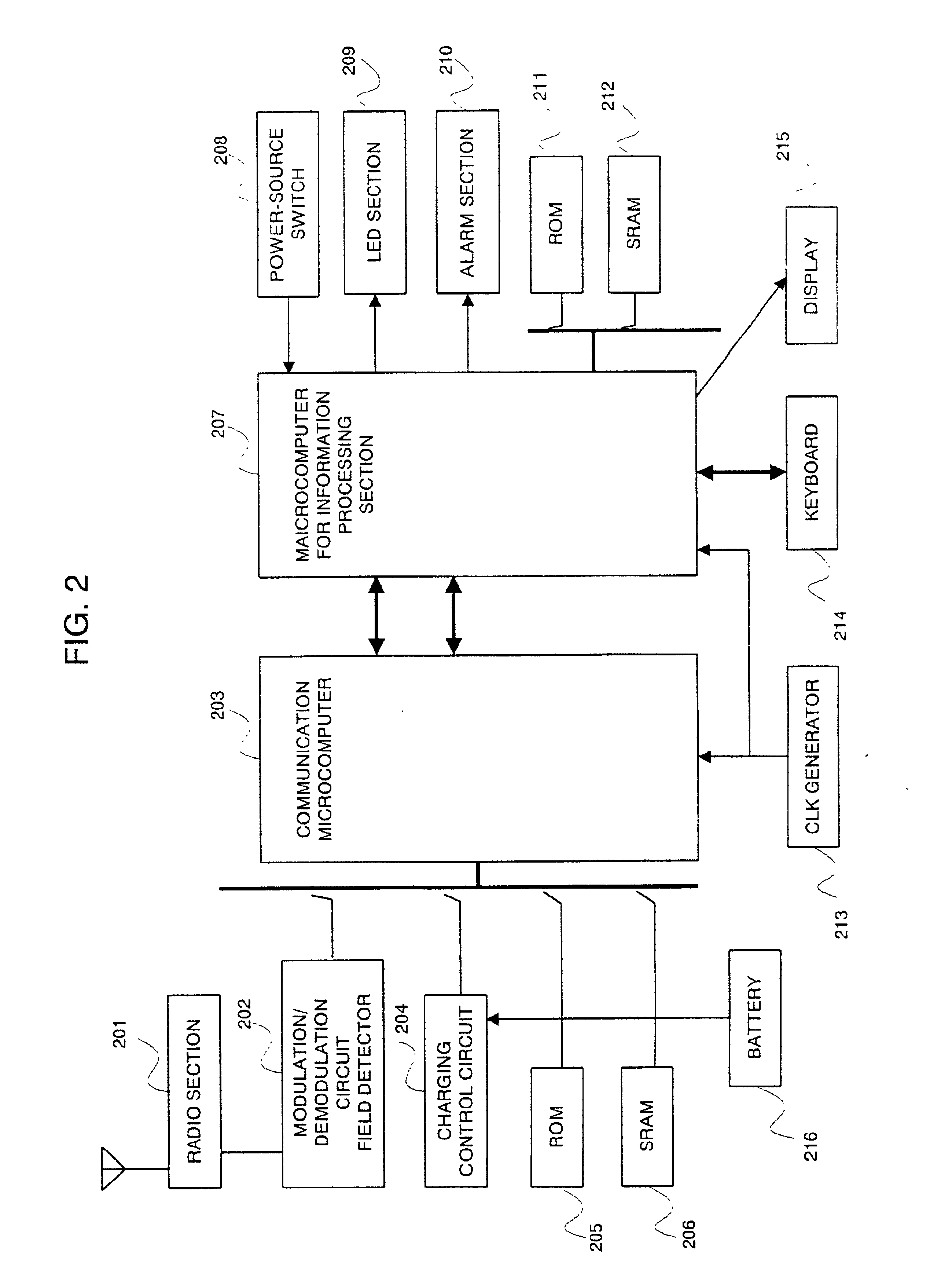
FIG. 2 shows the whole configuration of the first embodiment applied to a portable phone built-in portable terminal of the present invention. In the portable terminal related to the present embodiment shown in FIG. 2, a communication microcomputer 203 and an information-processing microcomputer 207 form a core section. The combination of a radio section 201 that transmits and receives radio waves and a modulation / demodulation circuit 202 work as a peripheral circuit of the communication microcomputer 203. The modulation / demodulation circuit 202 includes an electric field detector. The electric field detector detects the received levels of signals from the base station 103 received by the antenna and then creates information representing the received level.

The communication microcomputer 203 operates according to the program information set in the ROM (Read-Only Memory) 205 and mainly executes a data transmission / reception process related to a radio layer. Moreover,...

second embodiment

(Second Embodiment)

Next, the second embodiment according to the present invention will be described below. In the first embodiment of the present invention, the case where the process is carried out in accordance with the electronic mail receive protocol has been explained (referring to FIGS. 5 and 6). However, the present invention is applicable to protocols for FTP server (file transfer), HTTP (home page browsing) server, and TELNET (remote access). Any one of those protocols can avoid connections maintained to the server by executing the logging-out command in accordance with the protocol when the line quality, electric field level, or battery level is dropped.

In the first embodiment of the present invention, the case where the present invention is embodied to a portable-phone built-in terminal has been explained. However, the present invention is readily applicable to personal computers and portable terminals or to personal computers and portable terminals (PDA). In such a case,...


PUM


Abstract

The communication device includes a communication microcomputer 203 and an information-processing microcomputer 207. The communication microcomputer 203 has a line quality measuring section 301, a battery level measuring section 302, a data table 304, and a data transmission / reception decision section 303. The information-processing microcomputer 207 has a data transmission / reception prediction section 307 and a communication processing section 305. The electric field level, degradation in line quality, and the remaining amount of a battery are periodically monitored during data communication such as electronic mail reception. The data transmission / reception decision section 303 implements a decision process based on various predetermined information sets acquired through the monitoring. When deciding that the line is disconnected during communication, the data transmission / reception decision section 303 interrupts the mail reception and performs a logging-out with the server, thus disconnecting the line. As a result, it can be avoided that the connection between the terminal and the server is maintained.

Description

BACKGROUND OF THE INVENTIONThe present invention relates to a communication device and a communication method, each suitable in use for mobile communication equipment, typically, portable terminals (PDAs).Conventionally, there is the technique of connecting a portable phone to a notebook personal computer (PC) or portable terminal (PDA), which uses a battery and can be readily carried, to exchange electronic mails or to have access to the Internet. Portable terminals, each incorporating a radio module, are available in the market. Such a portable terminal has made it possible to easily access servers through the Internet during movement.For example, JP-A No. 145862 / 1998 discloses the radio data communication card that restricts the calling operation of a portable phone when the receive level of radio waves from a base station is less than a prescribed value. Moreover, JP-A No. 286324 / 1987 discloses the portable phone that reduces its transmission power when the output voltage value ...

Claims


Application Information

Patent Timeline
IPC IPC(8): H04B17/00H04L12/28H04Q7/22H04Q7/38H04B7/26H04W24/00H04W24/08H04W28/00H04W52/02H04W76/06H04W88/02
CPCH04B17/20H04W24/00H04W52/0296H04W76/06H04W76/30Y02D30/70
Inventor MURAMATSU, TOSHIHIKO
Owner LENOVO INNOVATIONS LTD HONG KONG
Learn More