System and method for airborne wind energy production

a technology of airborne wind and energy production, applied in the direction of gliders, machines/engines, transportation and packaging, etc., can solve the problems of large dead time of methods and relatively poor integrated energy yield, and achieve the highest lift force, the effect of reducing the number of turbines and increasing the energy yield

Inactive Publication Date: 2014-12-11
AMPYX POWER
View PDF10 Cites 28 Cited by
  • Summary
  • Abstract
  • Description
  • Claims
  • Application Information

AI Technical Summary

Benefits of technology

[0017]A glider provides the advantage of low aerodynamic resistance or drag and a high aerodynamic lift due to the fixed wing with rigid aerodynamic profile or airfoil, respectively. This is in particular beneficial, because the energy effectively extracted from the wind strongly depends on lift and drag, in particular on the so called lift-over-drag-ratio.
[0040]In the second flight pattern, which is in particular a low lift flight pattern, the glider for instance is brought in a descent towards the ground station. Here, the pull on the tether is reduced and eventually brought to zero. This way, minimum energy is consumed for spinning the reel, while no energy is required to pull the glider towards the ground station. At the same time, the speed of the glider towards the ground station is maximized and the dead time, i.e. the time required for system recovery, is minimized.

Problems solved by technology

However, this method suffers from a large dead time, because no energy is generated during rise and return of the kite.
Therefore, the integrated energy yield is relatively poor.

Method used


Image

  • System and method for airborne wind energy production
  • System and method for airborne wind energy production
  • System and method for airborne wind energy production

Examples


Embodiment Construction

[0050]In the drawings, the same or similar types of elements or respectively corresponding parts are provided with the same reference numbers in order to prevent the elements from needing to be reintroduced.

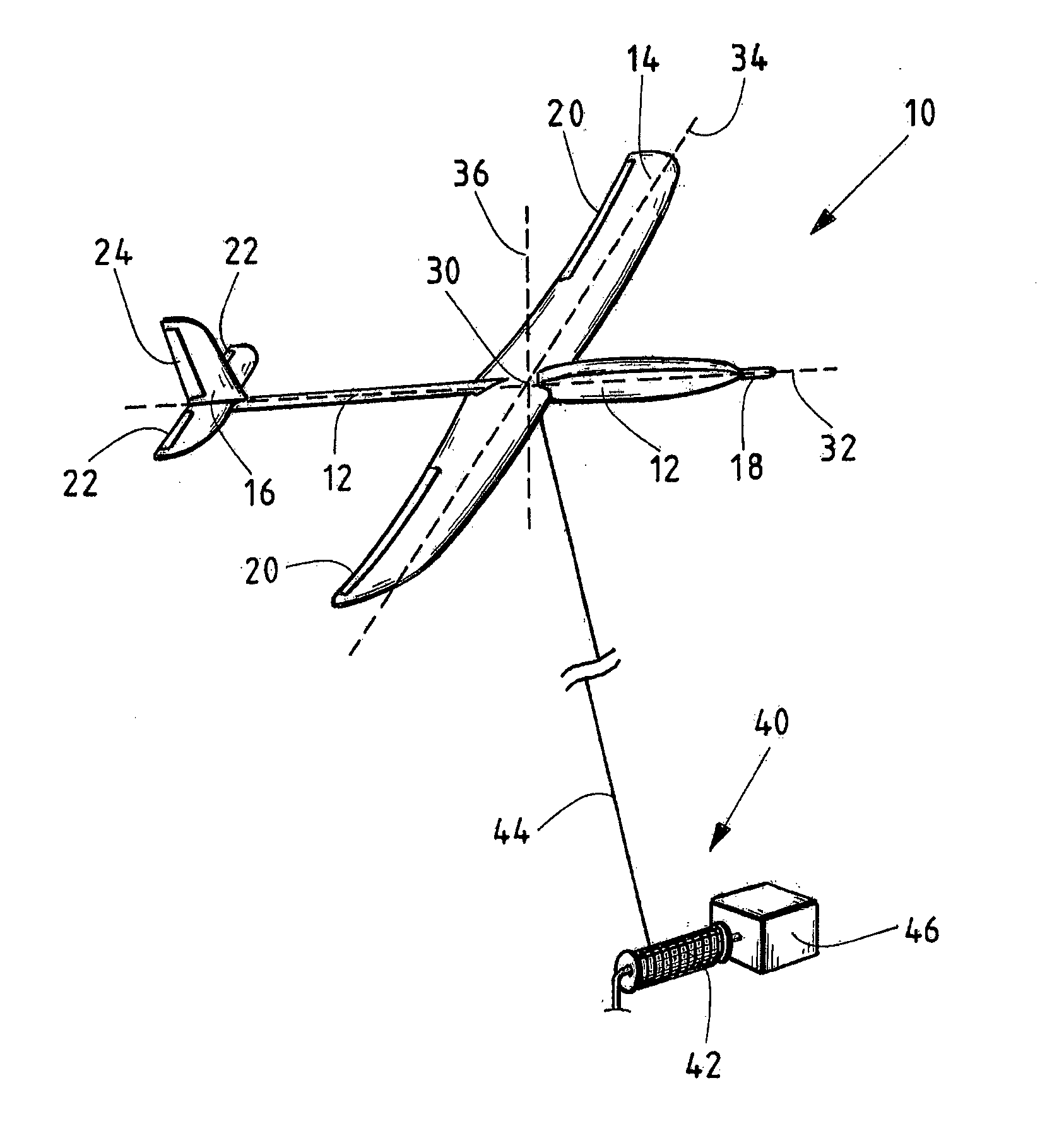
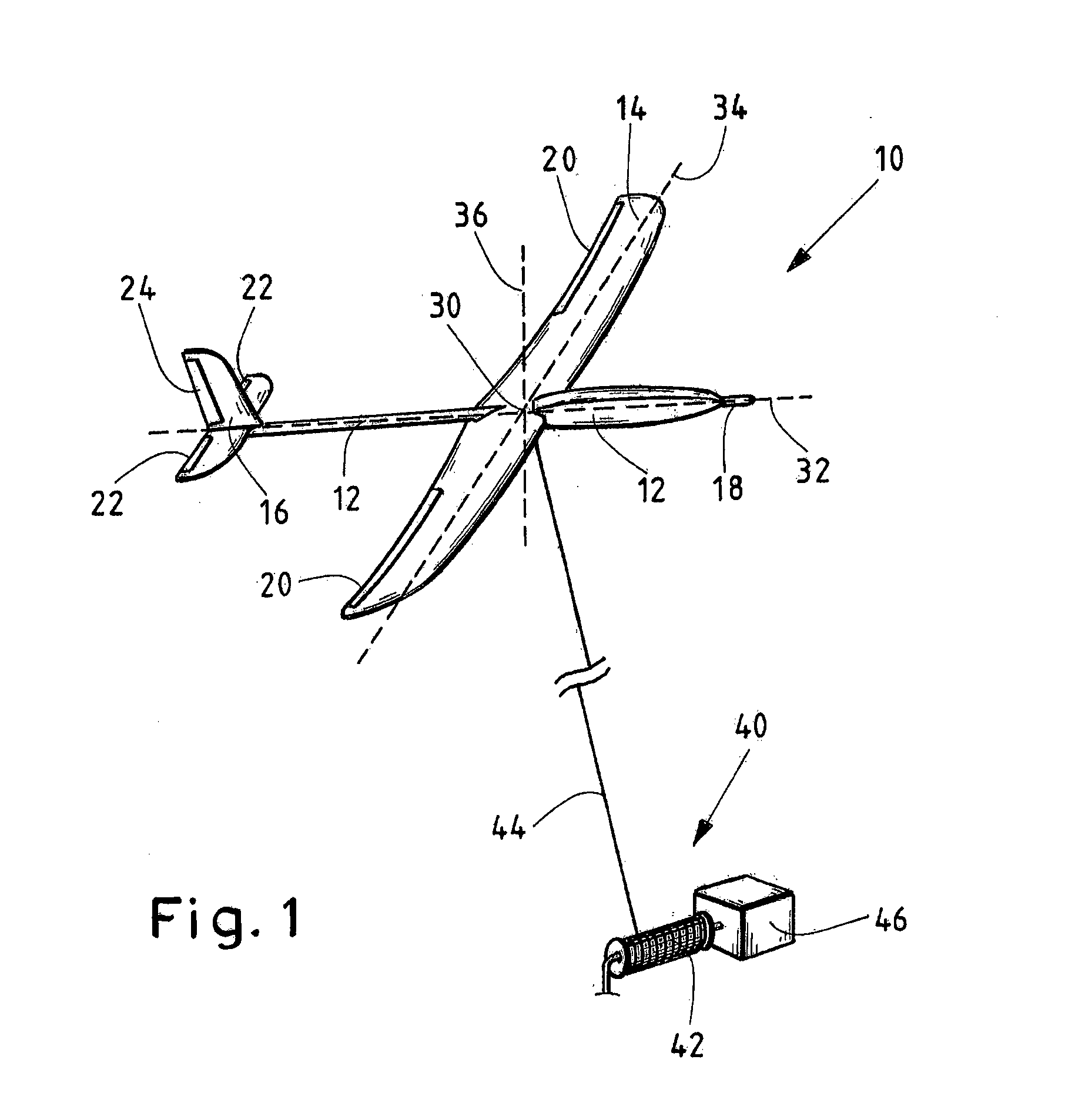
[0051]FIG. 1 shows an exemplary embodiment of a system for electric power production from wind according to the invention.

[0052]The airborne or potentially airborne part of the system comprises a glider 10, which in the embodiment depicted in FIG. 1 is designed to be a fixed wing aircraft. The glider 10 comprises a fuselage 12, a main wing 14, a tailplane 16 and control surfaces 20, 22, 24. Also shown are the longitudinal axis 32, the lateral axis 34 and the vertical axis 36, which meet at the centre of gravity 30 of the glider and which constitute the intrinsic coordinate system of the glider.

[0053]In the example shown, the fuselage 12 comprises a tube constructed from fiber reinforced composite material as mechanical backbone between the main wing 14 and the tailplane 16 and a ...


PUM


Abstract

A system for electric power production from wind includes a glider having an airfoil, an on-board steering unit, a flight controller for controlling the steering unit, and a connection unit for a tether. The system further includes a ground station including a reel for the tether, a rotating electrical machine connected to the reel, and a ground station controller for controlling the reel and the rotating electrical machine. A master controller operates the system in at least first and second operation modes. In the first operation mode electric power is produced with the rotating electrical machine from rotation of the reel caused by reeling out the tether using a lift force generated upon exposure of the airfoil of the airborne glider to wind. In the second operation mode, the reel is driven by the rotating electrical machine, thereby reeling in the tether onto the reel.

Description

BACKGROUND OF THE INVENTION[0001]1. Field of the Invention[0002]The present invention generally relates to a system for electric power production from wind and, more particularly, to a method for operation of a system for electric power production from wind, and to a glider for a system for production power from wind and to the use of a glider for production of electric power from wind.[0003]2. Description of Related Art[0004]The production of electric power from wind is generally accomplished by airfoils or structures with an aerodynamic profile, which produce lift forces upon exposure to wind. Thereby, energy is extracted from the wind, and the energy can be converted into electricity by, for example, using the lift forces to drive an electrical generator. Well known wind turbines include a rotor with aerodynamically profiled rotor blades, wherein the lift forces of the rotor blades cause the rotor to turn. The rotor is mounted to an electrical generator that is, for example, loca...

Claims


Application Information

Patent Timeline
Patent Type & Authority Applications(United States)
IPC IPC(8): B64C39/02F03D5/02H02G11/02F03D9/00B64C31/02B64C19/00
CPCB64C39/022B64C31/02B64C19/00F03D5/02H02G11/02F03D9/003B64C39/024F03D5/00F05B2240/92F05B2240/921F05B2240/923F03D9/255Y02E10/728F03D13/20Y02E10/70
Inventor RUITERKAMP, RICHARD
Owner AMPYX POWER
Why Eureka
Try Eureka