Glider for airborne wind energy productions

a technology of airborne wind and electric power, which is applied in the direction of machines/engines, mechanical equipment, transportation and packaging, etc., to achieve the effects of reducing the total weight of the glider, reducing the aerodynamic resistance or drag, and high aerodynamic li

Active Publication Date: 2015-09-24
AMPYX POWER
View PDF16 Cites 9 Cited by
  • Summary
  • Abstract
  • Description
  • Claims
  • Application Information

AI Technical Summary

Benefits of technology

[0015]A glider provides the advantage of low aerodynamic resistance or drag and a high aerodynamic lift due to the fixed wing with rigid aerodynamic profile or airfoil, respectively. This is in particular beneficial, because the energy effectively extracted from the wind strongly depends on lift and drag, in particular on the so-called lift-over-drag-ratio.
[0016]The sensor means and control device of the glider according to the invention allow for unmanned flight, which reduces the total weight of the glider. Therefore, a larger amount of the total lift force generated by the airfoil is available for electric power production and thus increases the integrated energy yield.
[0017]For enhanced safety of the glider, the connection means in particular are arranged for releasable connection of a tether to the glider, wherein the tether is connecting or arranged for connecting the glider to a ground-based electrical machine.
[0018]The sensor means and control device also allow for automated optimization of the flight, in particular in order to maximize the lift force during the energy production phase and in order to minimize the pull on the tether during the recovery phase. Also, the flight during the recovery phase can be optimized for minimum duration.

Problems solved by technology

One of the challenges of airborne wind energy production is the transferal of energy extracted from the wind at high altitudes to the ground.

Method used


Image

  • Glider for airborne wind energy productions
  • Glider for airborne wind energy productions
  • Glider for airborne wind energy productions

Examples


Embodiment Construction

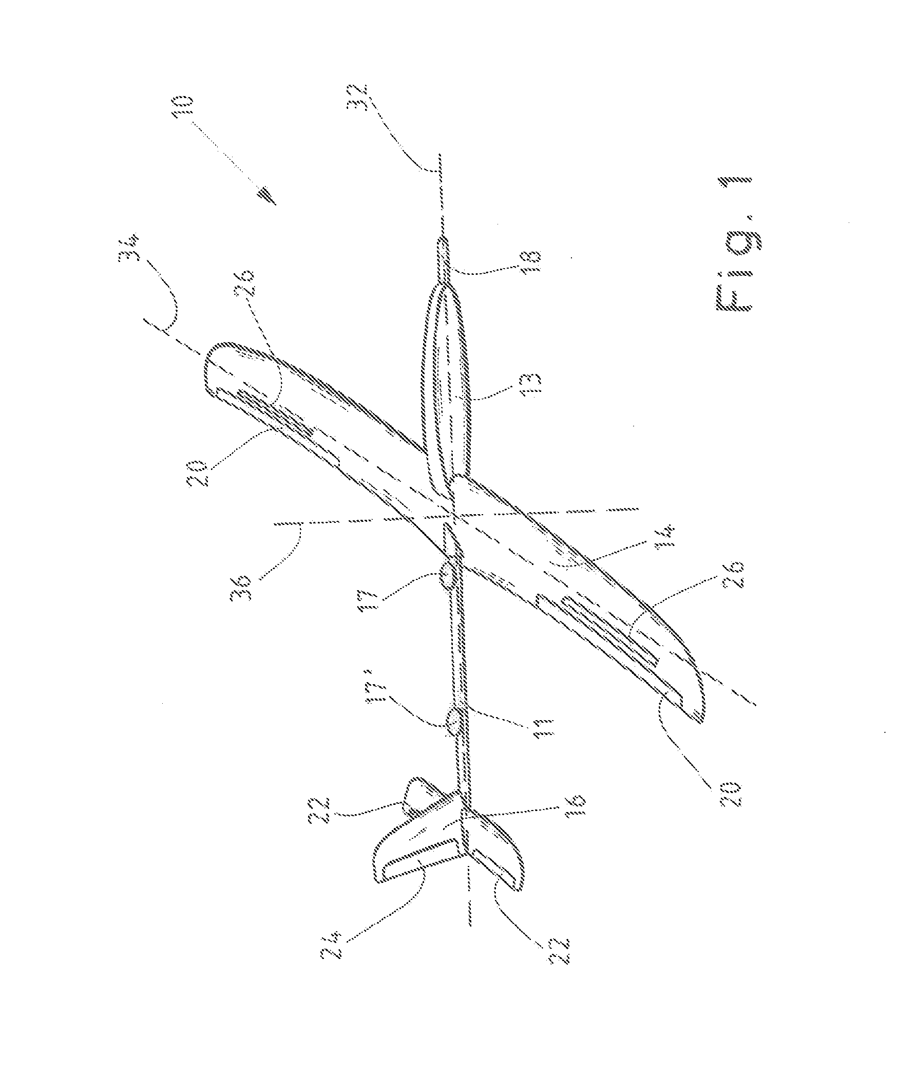
[0053]FIG. 1 shows an exemplary embodiment of a glider 10 for electric power production from wind 50 according to the invention.

[0054]The glider 10 is designed as a fixed wing aircraft comprising a fuselage, a main wing 14, a tailplane 16 and control surfaces 20, 22, 24. Also depicted in FIG. 1 are the longitudinal axis 32, the lateral axis 34 and the vertical axis 36, which meet at the center of gravity of the glider 10 and which constitute the intrinsic coordinate system of the glider 10.

[0055]In the example shown, the fuselage comprises a tube constructed from fiber reinforced composite material as mechanical backbone 11 between the main wing 14 and the tailplane 16 and a nacelle 13, which is mounted in front of the main wing 14.

[0056]The main wing 14 can for instance be constructed from a single wing, as in the embodiment depicted in FIG. 1. However, alternative designs, for instance with a separate main wing 14 on either side of the fuselage are within the scope of the inventio...


PUM


Abstract

A glider, a system and methods for electric power production from wind are disclosed. The glider includes an airfoil, onboard steering means for pitching, rolling and yawing the glider when airborne, sensor means that provide a first signal related to an absolute position of the glider, a second signal related to an air speed of the glider and a third signal related to an acceleration of the glider, a control device connected to the steering means for controlling autonomous flight of the glider based on the signals provided by the sensor means, and a connection means for a tether connecting the glider to a ground-based electrical machine constructed for converting a lift force generated upon exposure of the airfoil to wind and transferred to the ground via the tether into electric power. The system includes the glider, the ground-based electrical machine and tether.

Description

CROSS-REFERENCE TO RELATED APPLICATIONS[0001]This application is a continuation of International Application No. PCT / EP2013 / 002446, filed Aug. 14, 2013, and claims priority to EP 12181506.2, filed Aug. 23, 2012.BACKGROUND OF INVENTION[0002]1. Field of Invention[0003]The invention relates to a glider for electric power production from wind. The invention further relates to a system for electric power production from wind.[0004]2. Brief Description of Related Art[0005]The production of electric power from wind is generally accomplished by airfoils or structures with an aerodynamic profile, which produce lift forces upon exposure to wind. Thereby, energy is extracted from the wind, which can be converted into electricity, for example by exploring said lift forces to drive an electrical generator. Well known wind turbines for instance comprise a rotor with aerodynamically profiled rotor blades, wherein the lift forces of the rotor blades cause the rotor to turn. The rotor is mounted to ...

Claims


Application Information

Patent Timeline
Patent Type & Authority Applications(United States)
IPC IPC(8): B64C31/06F03D5/00
CPCB64C31/06F05B2240/921F03D5/00Y02E10/70Y02E10/72B64C39/022
Inventor RUITERKAMP, RICHARD
Owner AMPYX POWER
Why Eureka
Try Eureka