Operating device for an air vent and air vent

an air vent and operating device technology, applied in ventilation systems, lighting and heating apparatus, heating types, etc., can solve the problems of not being able to directly operate the rear vanes, the driver of the vehicle is distracted, and the vanes are swivel

Active Publication Date: 2014-12-11
ILLINOIS TOOL WORKS INC
View PDF8 Cites 9 Cited by
  • Summary
  • Abstract
  • Description
  • Claims
  • Application Information

AI Technical Summary

Benefits of technology

[0006]It is an object of the invention to provide an operating device for an air vent which allows a simple and intuitive operation of an air vent. A further object of the invention is to provide an air vent having such an operating device.
[0007]To achieve the object, provision is made for an operating device for an air vent which includes at least one swiveling vane, the operating device including a first operating lever which has a first lever arm, a second lever arm, and a bearing member which is arranged therebetween, the first operating lever being mounted around the bearing member for swiveling about a swivel pin, and including a second operating lever which has a first lever arm, a second lever arm, and a bearing member which is arranged therebetween, the second operating lever being mounted around the bearing member for swiveling about a swivel pin. The first lever arm of the second operating lever is coupled to the second lever arm of the first operating lever, and the second lever arm of the second operating lever is adapted to be coupled for swiveling motion to the vane. Both operating levers can be mounted in the air vent with the bearing members, for example at a front vane as viewed from the interior of the vehicle. The mode of functioning of the first operating lever corresponds to that of a lever as is known from an air vent from the prior art, which is firmly connected with an operating element and can be swiveled jointly with it. According to the invention, a second operating lever is arranged between this first operating lever and the vane and can also be mounted for swiveling motion in the air vent. The second operating lever is connected for swiveling motion both with the first operating lever and the vane and can be swiveled about the bearing member. Since the second operating lever is coupled to the first operating lever, it is swiveled in opposition to the first operating lever, by analogy with the vane of an air vent known from the prior art. The vane coupled to the second operating lever is, in turn, swiveled in opposition to the second operating lever, that is, in the same direction as the first operating lever. This causes the vane to be swiveled each time in the swivel direction of the first operating lever or of an operating member provided on the first operating lever. As a result, this allows a more intuitive operation of an air vent having such an operating device since the swiveling of the vanes and, hence, the deflection of the air always occurs in the direction in which an operating member is swiveled.
[0008]Particularly in an air vent having two pairs of vanes that are perpendicular to each other, a considerably simpler operation is possible. The operating device is mounted, for example, on a front vane as viewed from the interior of the vehicle, the first operating lever being adapted to be operated from the interior of the vehicle. The front vane can be operated by swiveling the first operating lever and, thus, the entire operating device. By swiveling the first operating lever in the plane of the front vanes, the rear vane is adjusted by means of the operating device according to the invention, the rear vane likewise being adjusted each time in the swivel direction of the first operating lever. This means that both pairs of vanes are each time swiveled in the direction of actuation of the operating device, allowing an intuitive operation.

Problems solved by technology

Where provision is made for two groups of vanes arranged one behind the other, for example perpendicular to each other, it is not possible to directly operate the vanes positioned at the rear as viewed from the interior of the vehicle because they are covered by the front vanes.
These operating devices have the drawback that the rear vanes are swiveled in opposition to the swivel direction of the operating member, whereas the swivel direction of the front vanes corresponds to the swivel direction of the operating member.
This requires a frequent rethinking on the part of the vehicle occupant, which may cause the driver of the vehicle to be distracted.

Method used


Image

  • Operating device for an air vent and air vent
  • Operating device for an air vent and air vent
  • Operating device for an air vent and air vent

Examples


Embodiment Construction

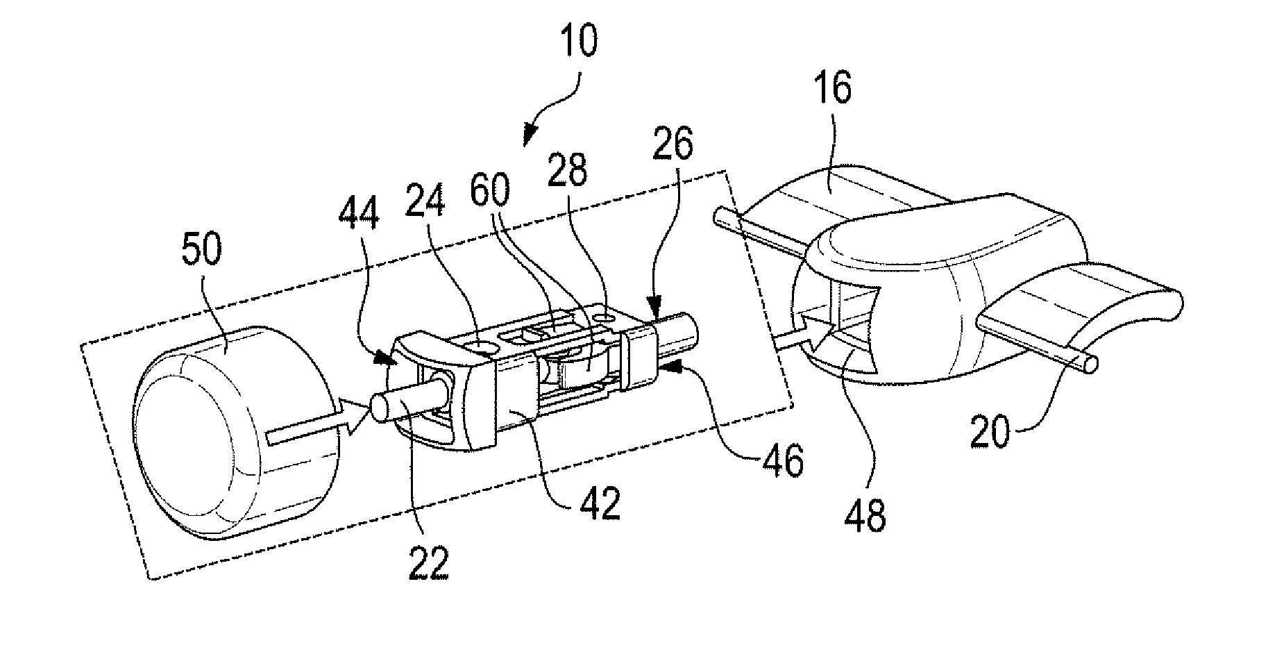
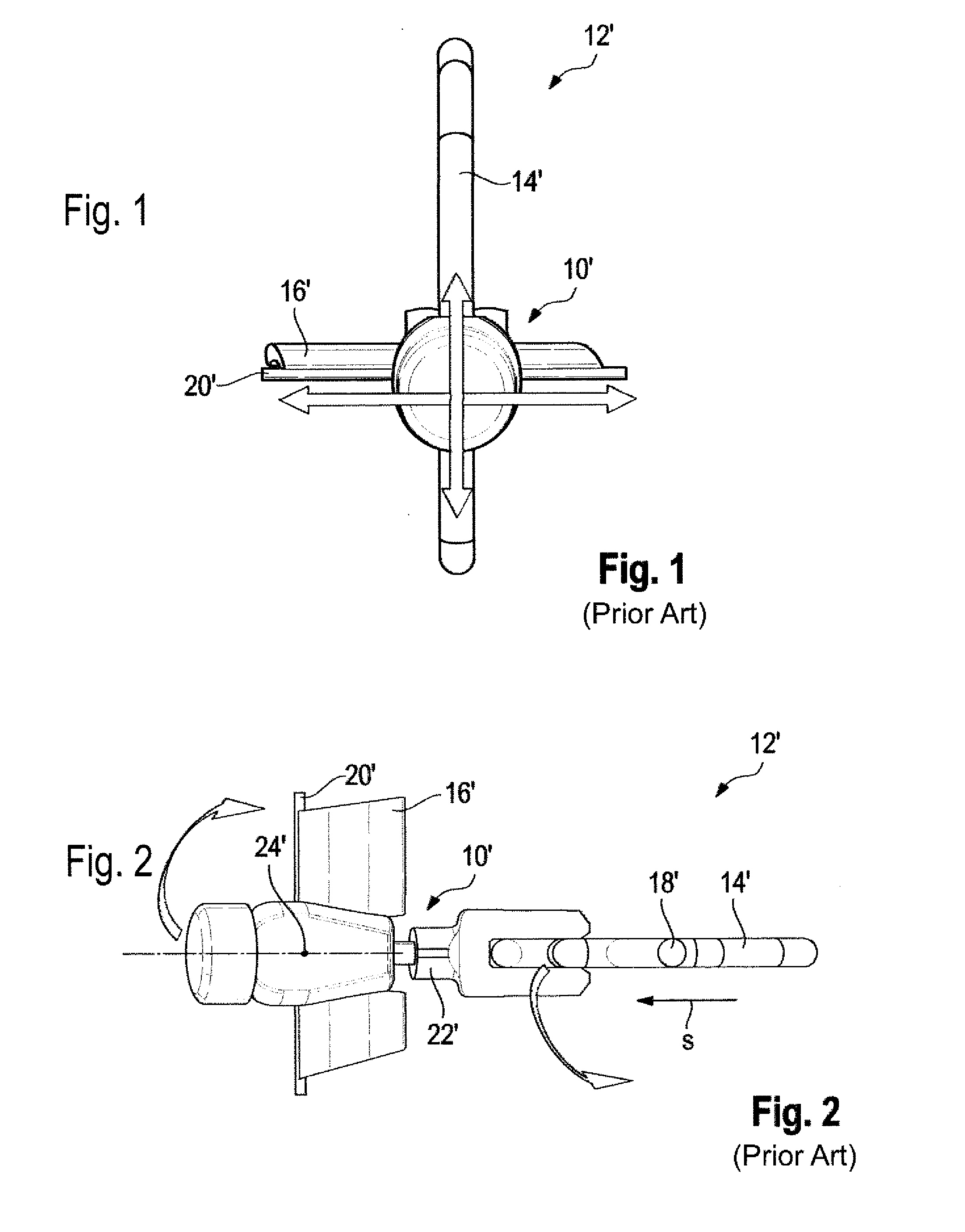
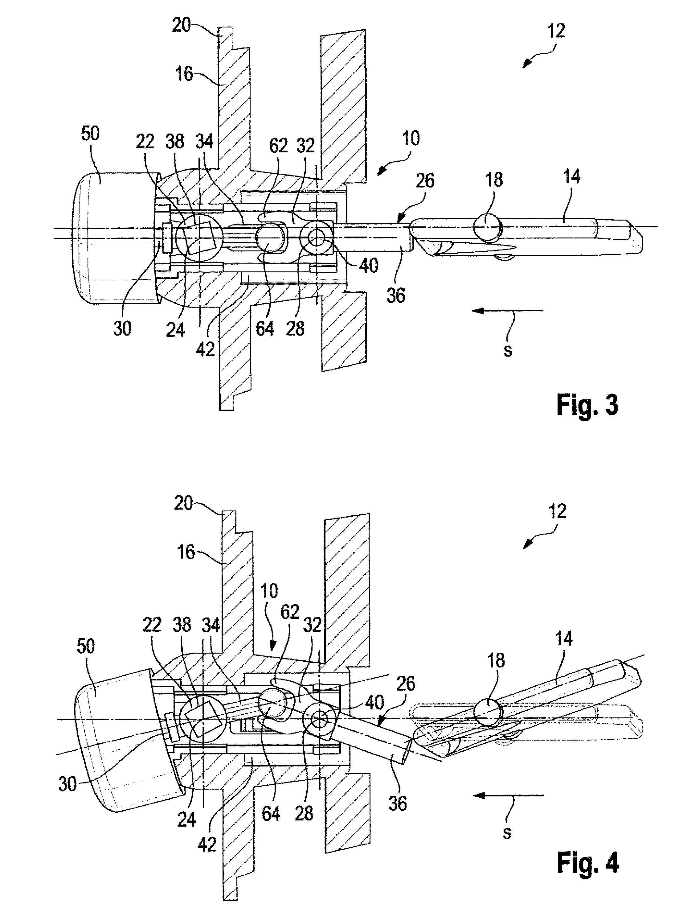
[0027]FIGS. 1 and 2 show an operating device 10′ from the prior art in an air vent 12′ of which only parts are illustrated here. The air vent 12′ has a first, rear vent 14′ as viewed from the vehicle interior and a second, front vane 16′ as viewed from the vehicle interior. The two vanes are each adapted to be swiveled about a swivel pin 18′, 20′.

[0028]The air vent 12′ includes further vanes, not illustrated here, which are arranged parallel to the first and second vanes 14′, 16′, respectively. The parallel vanes are each coupled to the first or to the second vane 14′, 16′, so that they can be swiveled jointly with the first or the second vane 14′, 16′.

[0029]The operating device 10′ includes an operating lever 22′ which is mounted on the second vane 16′ for swiveling about a swivel pin 24′. As is shown in FIG. 2, the operating lever 22′ is coupled for swiveling motion to the first vane 14′.

[0030]When the operating lever 22′ is swiveled upwards or downwards in relation to FIG. 1, the...


PUM


Abstract

An operating device (10) for an air vent (12) which includes at least one swiveling vane (14), the operating device (10) having a first operating lever (22) which has a first lever arm (30), a second lever arm (34), and a bearing member (38) which is arranged therebetween, the first operating lever (22) being mounted around the bearing member (38) for swiveling about a swivel pin (24), and a second operating lever (26) which has a first lever arm (32), a second lever arm (36), and a bearing member (40) which is arranged therebetween, the second operating lever (26) being mounted around the bearing member (40) for swiveling about a swivel pin (28), the first lever arm (32) of the second operating lever (26) being coupled to the second lever arm (34) of the first operating lever (22) and the second lever arm (36) of the second operating lever (26) being adapted to be coupled for swiveling motion to the vane (14).

Description

BACKGROUND OF THE INVENTION[0001]The present invention relates to an operating device for an air vent including at least one swiveling vane. The invention further relates to an air vent.[0002]Air vents having vanes for deflecting the airstream include, for example, a central operating member for swiveling the vanes. Where only one group of vanes is provided, with the vanes being parallel and coupled to each other, the operating member is attached directly to one of the vanes, so that by moving the operating member, the vanes can be swiveled directly in the direction in which the operating member is swiveled.[0003]Where provision is made for two groups of vanes arranged one behind the other, for example perpendicular to each other, it is not possible to directly operate the vanes positioned at the rear as viewed from the interior of the vehicle because they are covered by the front vanes. But it is desirable for reasons of convenience to swivel both groups of vanes using one operatin...

Claims


Application Information

Patent Timeline
Patent Type & Authority Applications(United States)
IPC IPC(8): B60H1/34F24F13/14
CPCB60H1/3421F24F13/1426F24F13/1486F24F2013/1473B60H2001/3471B60H2001/3464
Inventor NOICHL, HARALDMOOTZ, FRANK
Owner ILLINOIS TOOL WORKS INC
Why Eureka
Try Eureka