

Blocked valve isolation tool
- Summary
- Abstract
- Description
- Claims
- Application Information
AI Technical Summary
Benefits of technology
Problems solved by technology
Method used
Image

Examples
first embodiment
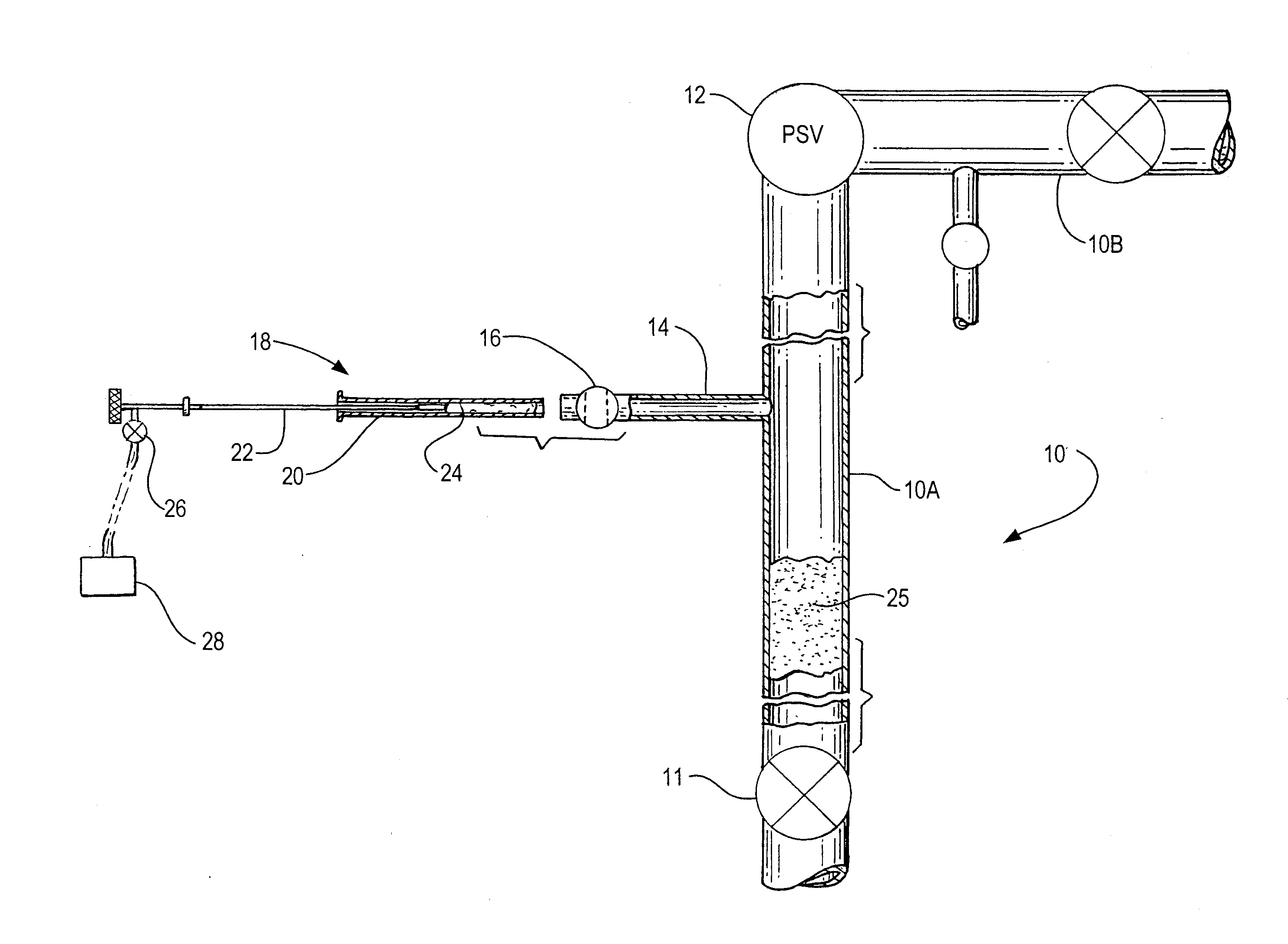
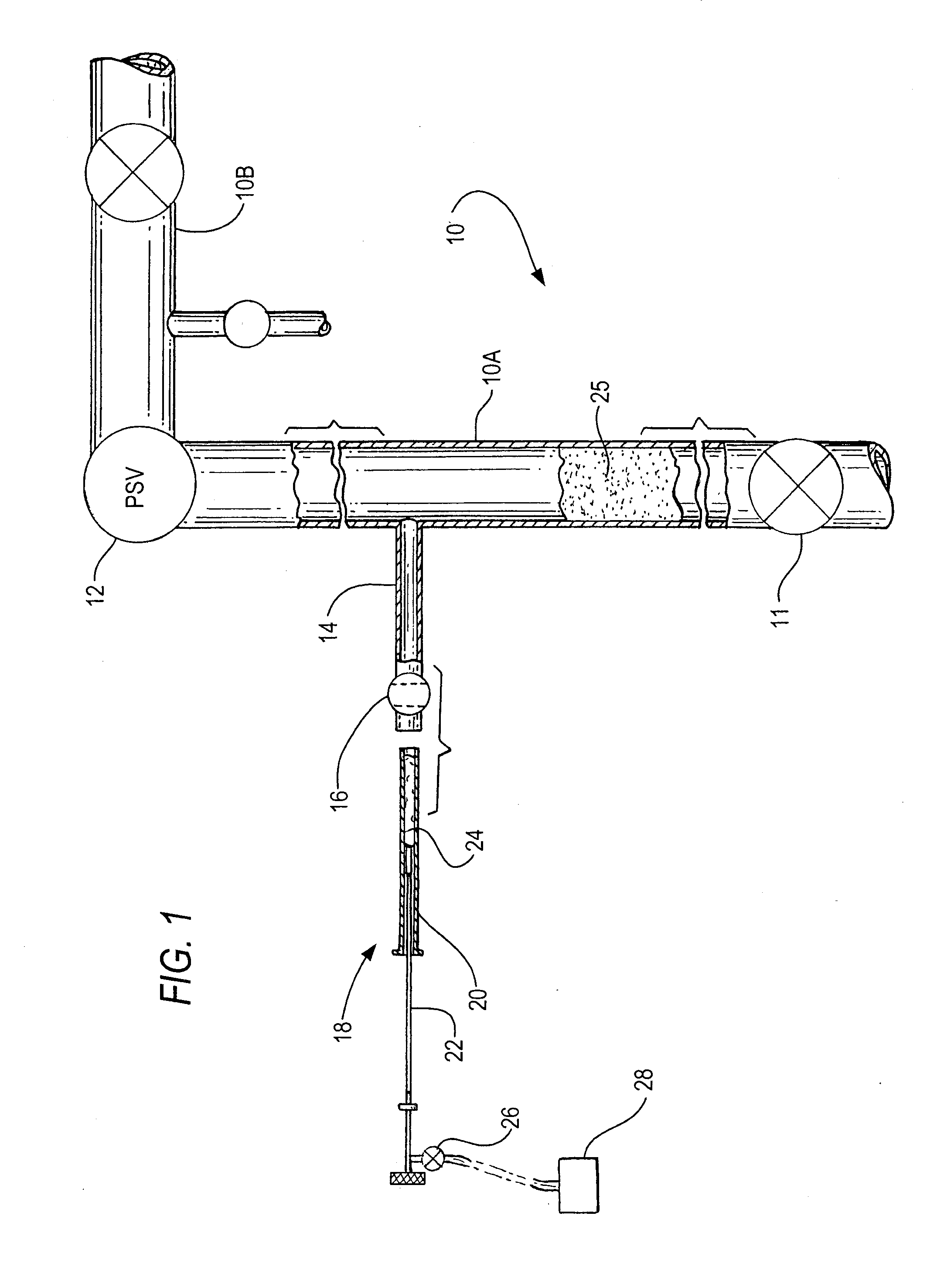
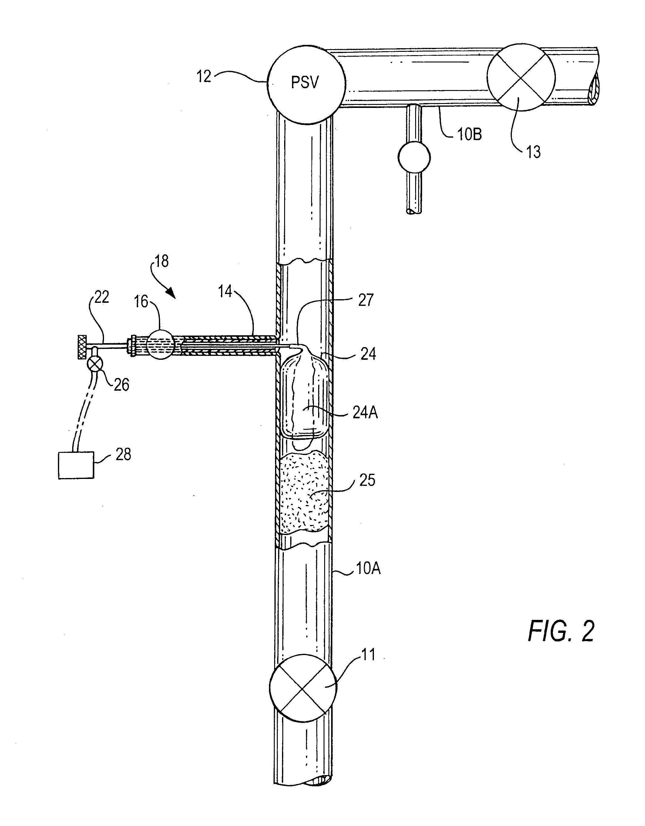
[0043]FIGS. 1 through 3 illustrate the present invention as a device operable in a duct system through which flows a gas that should be prevented from escaping while a downstream valve is inspected, removed, repaired and / or replaced. The relevant duct system includes an upstream duct 10A, relief valve 12 and further duct 10B downstream of relief valve 12. A gas flows through this duct 10A-10B with relief valve 12 in line to monitor pressure of the gas flow and relieve excessive pressure if such occurs; however, periodically the relief valve needs to be isolated, inspected and as required removed, repaired or replaced and re-installed. A principal object of this invention is to allow an efficient inspection, repair and / or replacement of a relief valve without having to shut down significant portions of the system, particularly the duct 10A-10B where the relief valve is located.
[0044]As seen in FIGS. 1 and 2, extending transversely out of duct 10A, is vent duct 14, blocking valve 16 a...
second embodiment
[0054]FIGS. 4 and 5 illustrate the new invention which has the features of the embodiment of FIGS. 1-3 plus a rubber cover 30 designed to create a gas seal about valve isolation tool 18, so that gas which leaks or flows through blocking valve 11 cannot escape out through duct 14 and / or through valve 16 or other parts of isolation tool 18.
[0055]FIG. 4 shows cover 30 as a balloon-like element encompassing the proximal part of isolation tool 18, with the cover's proximal end 30A secured about the near end of inner tube 22 and its distal end 30B (shown stretched open for clarification) encompassing part of outer tube 20. FIG. 5 shows isolation tool 18 fully inserted through duct 14, and the distal end 30B of cover 30 secured about the near end of duct 14. FIG. 5 illustrates how cover 30 blocks escape of any gas that flows or leaks past valve 11 into duct 14, or flows upstream from relief valve 12 and into and through duct 14 and into components of isolation tool 18. The cover's distal e...
PUM
 Abstract
Description
Claims
Application Information