Device and method for providing power to optical network utilities

a technology for optical network utilities and devices, applied in the field of power systems, can solve problems such as the difficulty of providing power to the nus

Active Publication Date: 2014-12-18
STERLITE NETWORKS LIMTED
View PDF1 Cites 8 Cited by
  • Summary
  • Abstract
  • Description
  • Claims
  • Application Information

AI Technical Summary

Benefits of technology

[0015]In one aspect, the present invention discloses a device for providing power to one or more Network Utilities (NUs) in an optical network, which is used to provide communication to a plurality of devices of subscribers. The device includes one or more Power over Ethernet (POE) adapters operatively coupled to the plurality of devices of the subscribers. The one or more POE adapters are configured to derive AC power and data signals from the plurality of devices, and convert the derived AC power into DC signals. Further, the device includes at least one Power over Ethernet (POE) splitter operatively coupled to the one or more POE adapters. The POE splitter is configured to split the DC signals from the data signals, and feed the DC signals to the one or more NUs for satisfying their po

Problems solved by technology

However it is generally observed that power source is not in proximity to t

Method used


Image

  • Device and method for providing power to optical network utilities
  • Device and method for providing power to optical network utilities
  • Device and method for providing power to optical network utilities

Examples


Embodiment Construction

[0030]The exemplary embodiments described herein detail for illustrative purposes are subject to many variations in structure and design. It should be emphasized, however, that the present invention is not limited to a particular device for providing power to NUs as described. It is understood that various omissions and substitutions of equivalents are contemplated as circumstances may suggest or render expedient, but these are intended to cover the application or implementation without departing from the spirit or scope of the present invention.

[0031]The terms “a” and “an” herein do not denote a limitation of quantity, but rather denote the presence of at least one of the referenced item.

[0032]The terms “having”, “comprising”, “including”, and variations thereof signify the presence of a component.

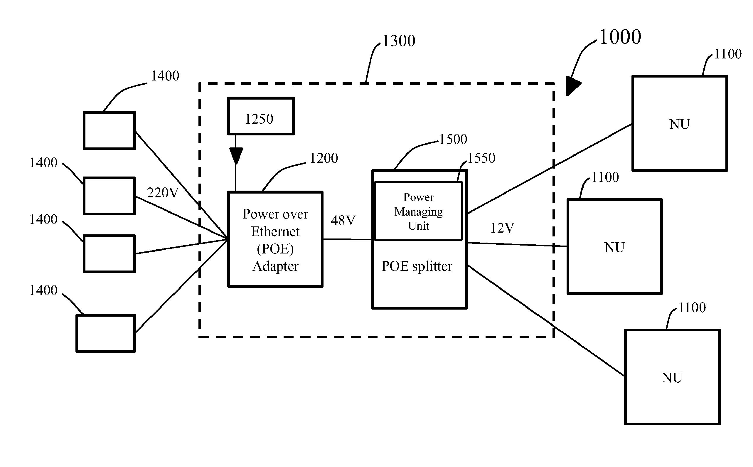
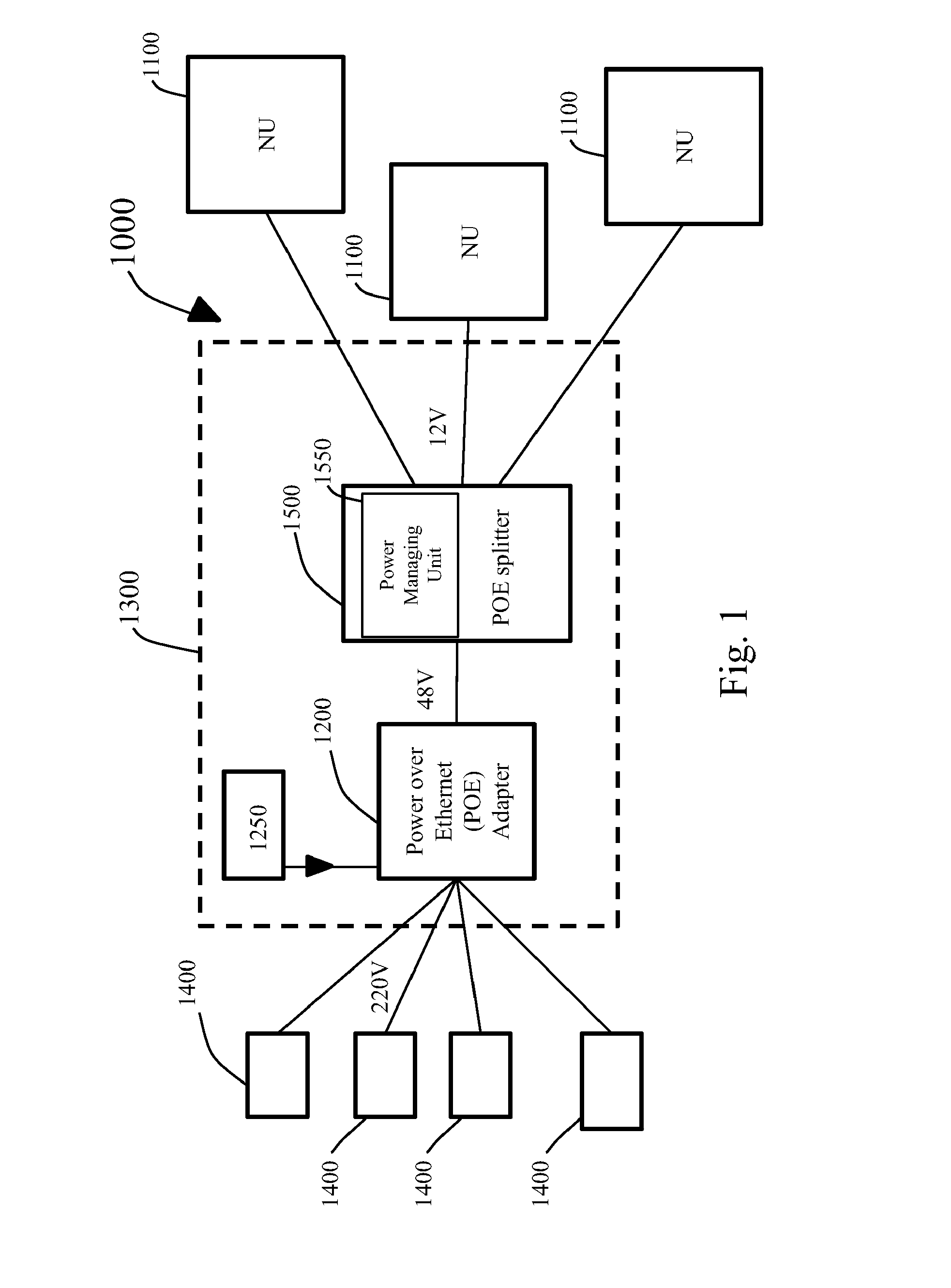
[0033]The present invention provides devices and methods for providing power to one or more Optical Network Utilities (OUs) in an optical network. It should be understood that the term Op...


PUM


Abstract

Disclosed is a device (1000) for providing power to one or more Optical Network Utilities (NUs) (1100) in an optical network (1300) used to provide communication to a plurality of devices (1400) of subscribers. The device (1000) includes one or more Power over Ethernet (POE) adapters (1200) operatively coupled to the subscriber devices. The POE adapters are configured to derive AC power and data signals from the plurality of devices, and convert the derived AC power into DC signals. Further, the device includes a Power over Ethernet (POE) splitter (1500) operatively coupled to the POE adapters. The POE splitter is configured to split the DC signals from the data signals, and feed the DC signals to the one or more NUs for satisfying their power needs.

Description

FIELD OF THE DISCLOSURE[0001]This invention relates to power systems, and more particularly, to device for providing power to various utilities in an optical network.BACKGROUND OF THE DISCLOSURE[0002]Various utilities called as Network Utilities or NUs are used in optical networks, such as hybrid fibre coaxial networks (HFCNs), for providing a variety of services, like telephony, cable television and internet, to subscribers. Examples of the NUs include Optical Network Units (ONUs), Optical Network Terminals (ONTs), and Optical Line Terminals (OLTs). ONUs are multiple subscriber devices installed near to a subscriber's complex for terminating any one of the endpoints of a fiber in order to provide multiple services to the subscribers. Similarly, Optical Network Terminals (ONTs) are installed at a subscriber's premises for converting fiberoptic light signals to copper / electric signals. The ONTs are generally disposed in an enclosure, generally called a telecom box, which is positione...

Claims


Application Information

Patent Timeline
IPC IPC(8): H04B10/80H04L12/10H04B10/27H02J3/02
CPCH04B10/808H04B10/27H04L12/10H02J3/02
Inventor JAIN, VIJAY
Owner STERLITE NETWORKS LIMTED
Why Eureka
Try Eureka