Object dimensioning apparatus, systems and related methods
a technology of object dimensioning and apparatus, applied in the field of taking dimensional measurements of objects, can solve the problems of insufficient space and unsuitability for measuring three-dimensional objects
- Summary
- Abstract
- Description
- Claims
- Application Information
AI Technical Summary
Benefits of technology
Problems solved by technology
Method used
Image

Examples
first embodiment
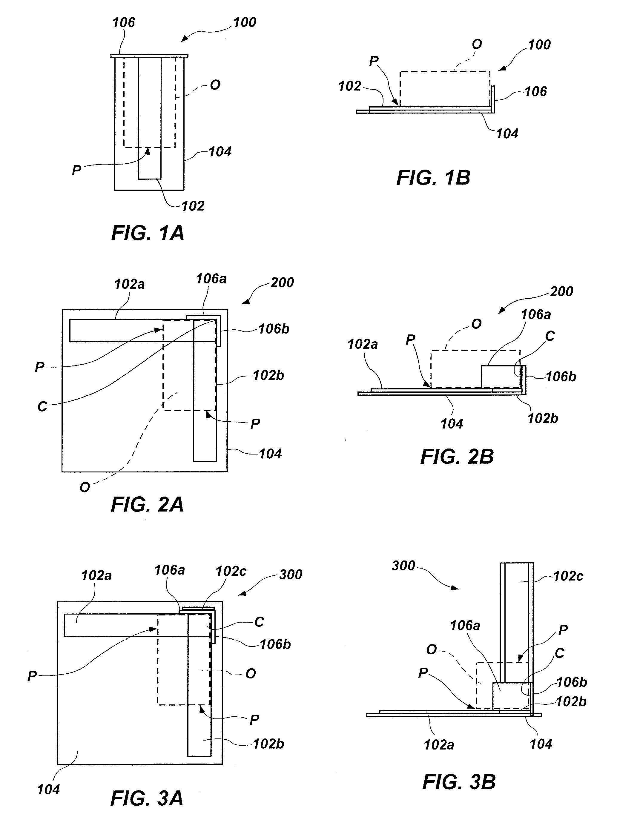
[0035]In a first embodiment, as illustrated in FIGS. 1A and 1B, a dimensional sensor apparatus 100, which may also be characterized as an object dimensioning apparatus, may comprise a linear sensor strip 102, which may also be characterized as a linear sensor element, mounted to a flat, rigid or flexible mat 104. Details of an embodiment of linear sensor strip 102 are described below, with reference to FIGS. 10A through 10E. Mat 104 may comprise, or be placed against, a rigid back surface 106 in use. A cuboidal object O (e.g., a box), as shown in broken lines, is placed on the strip with a first side against the back surface 106. The linear sensor strip 102 is then touched at a point P immediately adjacent to the side of the object opposite and parallel to the first side resting against the back surface 106. The resulting electrical signal is pre-calibrated and processed to produce a linear measurement (for example, object length) between the back surface 106 and touch point P. The ...
second embodiment
[0037]In a second embodiment, as illustrated in FIGS. 2A and 2B, a dimensional sensor apparatus 200, which may also be characterized as an object dimensioning apparatus, may comprise two linear sensor strips 102a and 102b, mounted at a 90° included angle and optionally to a flat, rigid or flexible mat 104. Two rigid back surfaces 106a, 106b create a 90° corner C at an apex of the included angle of the two linear sensor strips 102a, 102b. In use, a cuboidal object O, as shown in broken lines, is placed on the two linear sensor strips 102, 102b simultaneously, with a corner of the object nestled in the corner C between backing surfaces 106a, 106b. Each linear sensor strip 102a, 102b is then touched, either simultaneously or serially, at a point P immediately adjacent a side of the object O opposite and parallel to a respective side of object O resting against a back surface 106a or 106b. The resulting electrical signal from each touch is pre-calibrated and processed to produce a linea...
third embodiment
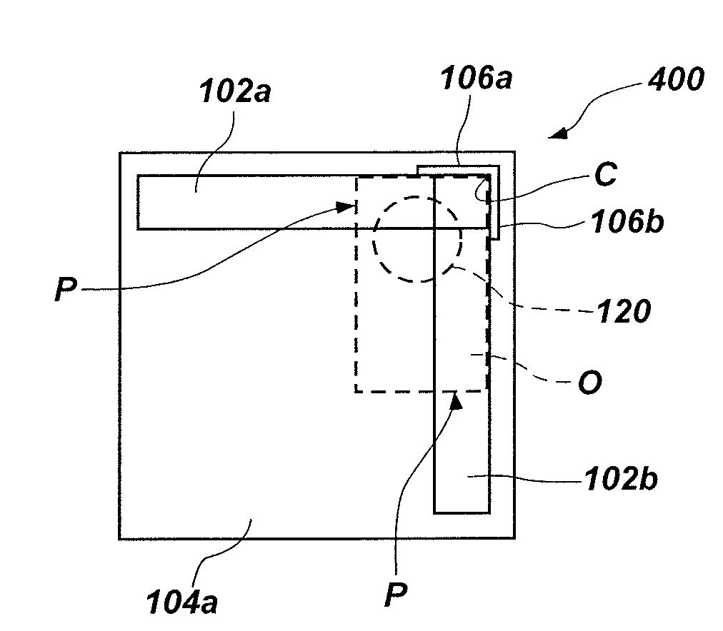
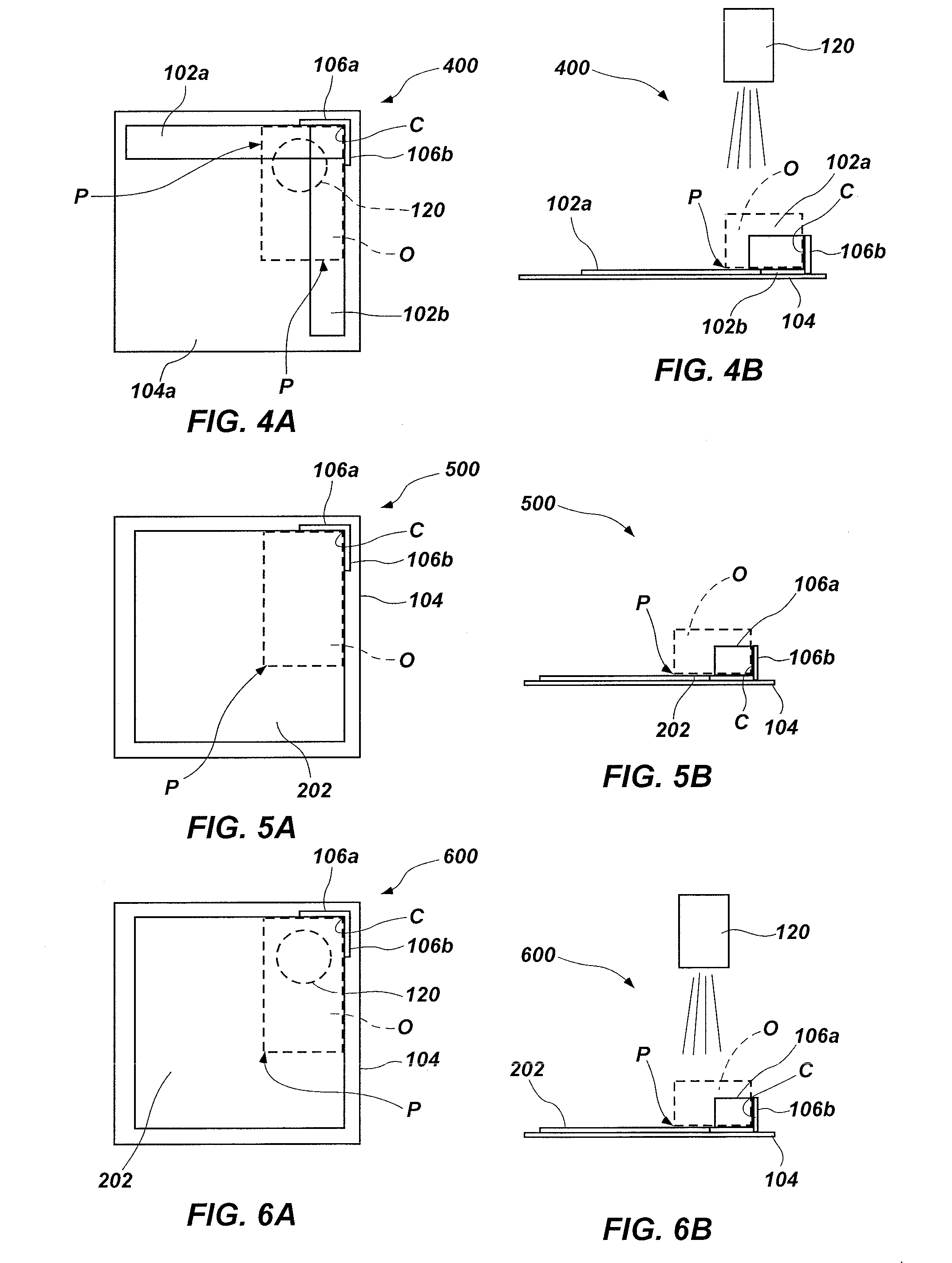
[0039]In a third embodiment, illustrated in FIGS. 3A and 3B, a dimensional sensor apparatus 300, which may also be characterized as an object dimensioning apparatus, may comprise two linear sensor strips 102a and 102b, mounted at a 90° included angle optionally to a flat, rigid or flexible mat 104. Two rigid back surfaces 106a, 106b create a 90° corner C at an apex of the included angle of the two linear sensor strips 102a, 102b. A third linear sensor strip 102c is mounted vertically adjacent to and substantially coplanar with one of the back surface 106a, 106b. In use, a cuboidal object O, as shown in broken lines, is placed on the two linear sensor strips 102a, 102b simultaneously with a corner of the object nestled in the corner C between back surfaces 106a, 106b and one side of object O adjacent to vertical linear strip 102c. Each linear sensor strip 102a, 102b, 102c is then touched, either simultaneously or serially, at a point P immediately adjacent a side of the object O oppo...
PUM
 Abstract
Description
Claims
Application Information
 - R&D
- Intellectual Property
- Life Sciences
- Materials
- Tech Scout
- Unparalleled Data Quality
- Higher Quality Content
- 60% Fewer Hallucinations
Browse by: Latest US Patents, China's latest patents, Technical Efficacy Thesaurus, Application Domain, Technology Topic, Popular Technical Reports.
© 2025 PatSnap. All rights reserved.Legal|Privacy policy|Modern Slavery Act Transparency Statement|Sitemap|About US| Contact US: help@patsnap.com