Device for enlarging caisson bases

a technology of caisson base and enlarging plate, which is applied in earth drilling, shaft sinking, mining structures, etc., can solve problems such as soil landslip and impose risks on the executor

Inactive Publication Date: 2014-12-25
TEIXEIRA WILSON ROBERTO
View PDF10 Cites 7 Cited by
  • Summary
  • Abstract
  • Description
  • Claims
  • Application Information

AI Technical Summary

Problems solved by technology

Currently, every soil excavating process for carrying out of base for caissons é performed manually, consisting of carrying out the same with a operator going down in the shank of caisson for enlarging the base, which process impose risks to the executor, incurring the possibility of soil landslip.

Method used


Image

  • Device for enlarging caisson bases
  • Device for enlarging caisson bases
  • Device for enlarging caisson bases

Examples


Embodiment Construction

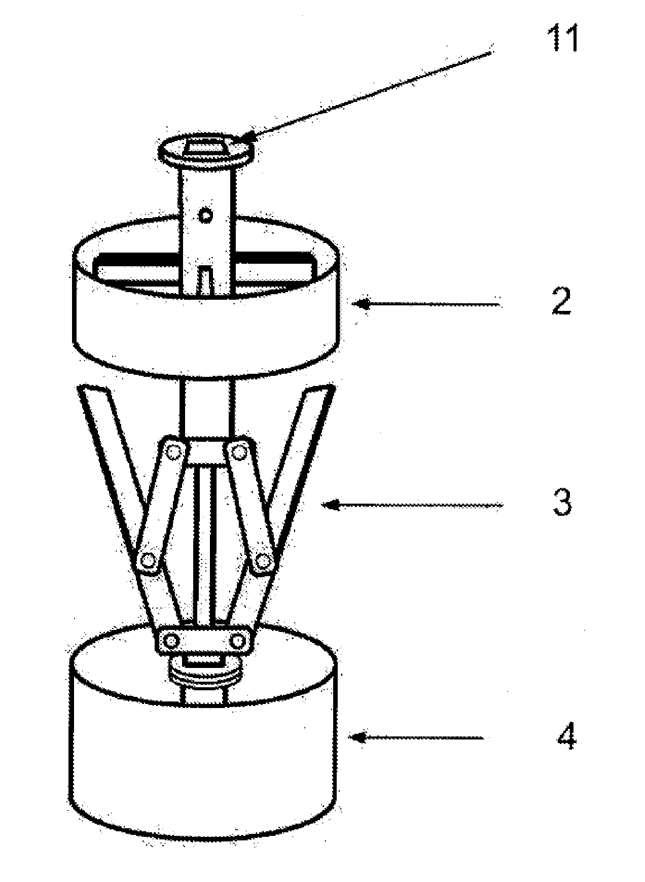
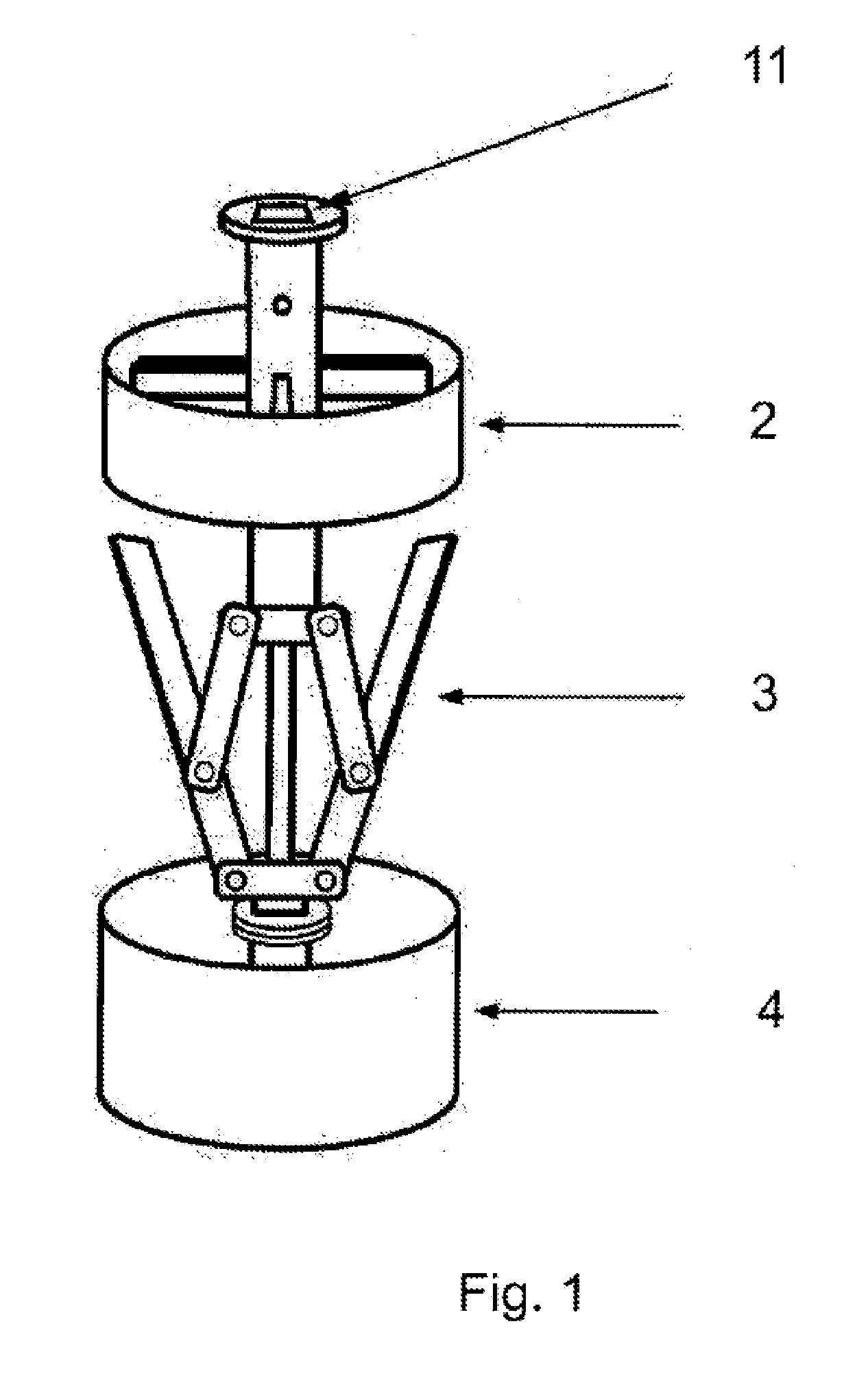
[0032]According to FIG. 1, it is possible to note the general feature of device for enlarging caissons, said device comprising, at upper extremity thereof, a socket (11) of engine shaft (1), a guide ring (2), a soil excavating mechanism (3), and a collector vessel for excavated soil (4).

[0033]Said soil excavating mechanism (3) and collector vessel of excavated soil (4) has cylindrical shape, which fits to diameter of caisson to be enlarged.

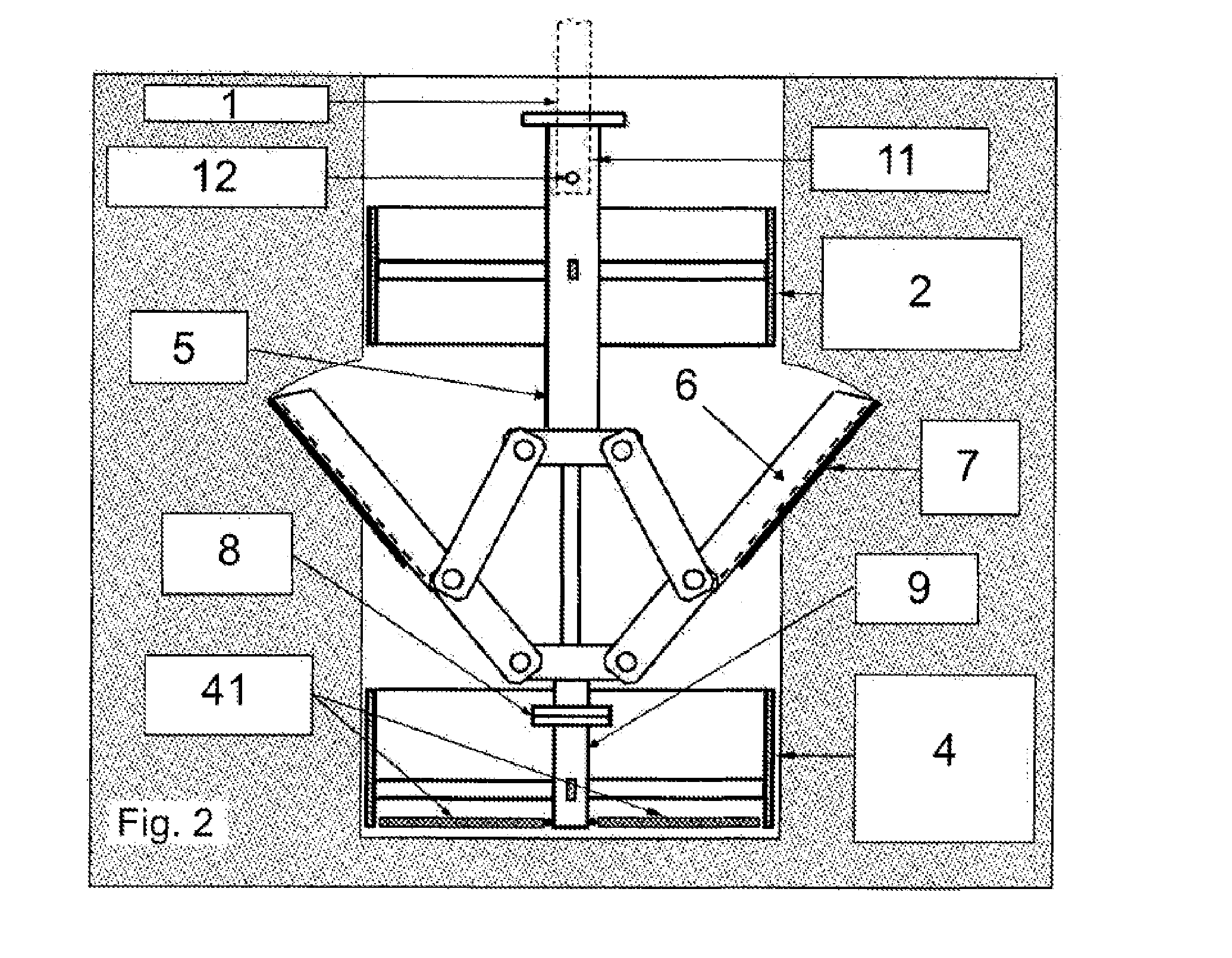
[0034]FIG. 2 shows the device in details, during the performance phase of enlarging a caisson base, wherein said device comprises, at upper extremity thereof, the socket (11) of engine shaft (1) of machine carrying out the mechanical excavating of caisson, wherein a fixation of shaft (1) in the socket (11) is made through a cylindrical fixation pin (12), said device comprises, at side arms (6) thereof, knives (7) which perform the enlarging of caisson base, and said device further comprises a collector vessel (4) of excavated soil at lower extremi...


PUM


Abstract

The present invention relates to a device used to mechanically enlarge the base de caissons, so as to form a semi-spherical cavity in the base de the caisson formed, in which said device includes a socket in the upper extremity thereof for the engine shaft, a guide ring, a soil excavating mechanism and a recipient for collecting the excavated soil.

Description

TECHNICAL FIELD[0001]This patent of invention application relates to a device to be used in mechanically enlarge of caisson bases, so that form a semi-spherical cavity at the base of caisson performed.[0002]Currently, every soil excavating process for carrying out of base for caissons é performed manually, consisting of carrying out the same with a operator going down in the shank of caisson for enlarging the base, which process impose risks to the executor, incurring the possibility of soil landslip.[0003]In this patent of invention application, the developed process has the purpose to remove the human figure of the process, avoiding burial risks and speeding up the base enlarging process, which is efficient in terms of reduction of execution time in the order of 80% or more.[0004]Some features of purpose of invention are:[0005]possibility of change in knives, which allows a opening of bases with different diameters;[0006]creation of a collector system facilitating the removal of e...

Claims


Application Information

Patent Timeline
Patent Type & Authority Applications(United States)
IPC IPC(8): E21B10/32E21D1/06
CPCE21D1/06E21B10/32E21B7/003E21B10/327
Inventor TEIXEIRA, WILSON R.
Owner TEIXEIRA WILSON ROBERTO
Why Eureka
Try Eureka