

Apparatus for indicating the location of a signal emitting tag
- Summary
- Abstract
- Description
- Claims
- Application Information
AI Technical Summary
Benefits of technology
Problems solved by technology
Method used
Image

Examples
first embodiment
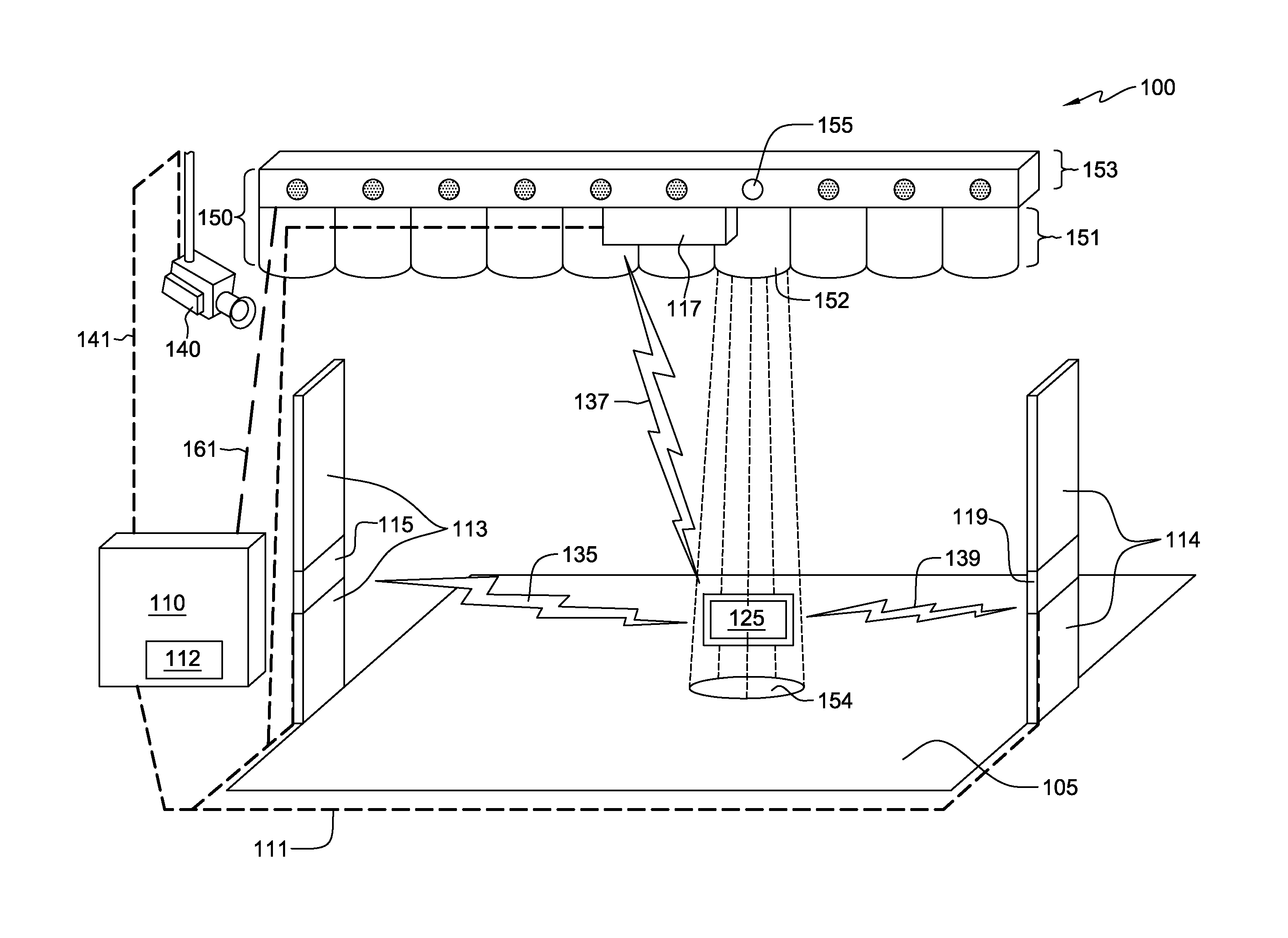
[0032]FIG. 1 is a block diagram, 100, illustrating a component layout for a detection system, 100, in accordance with the present invention. In FIG. 1, RFID detector 115 and 119 are located on opposite sides of surface 105. Both RFID detector 115 and 119 are illustrated as being integral with respective guide 113 and 114. The activation of light-beams 154 is shown illuminating the point of origin of a signal, i.e., signal emitter 125, which is located between RFID detector 115 and 119. Guide 113 and 114 are, in one embodiment, structures to limit the possible pathways of an individual carrying signal emitter 125. For example, guides 113 and 114 are placed at the outer edges of a doorway of a store. The placement of guide 113 and 114 encourages customers to cross surface 105 thereby allowing RFID detector 115, 117, and 119 an opportunity to detect a signal from signal emitter 125.
[0033]In some embodiments, guide 113, 114 include inductive coils that provide a source of power for sign...
second embodiment
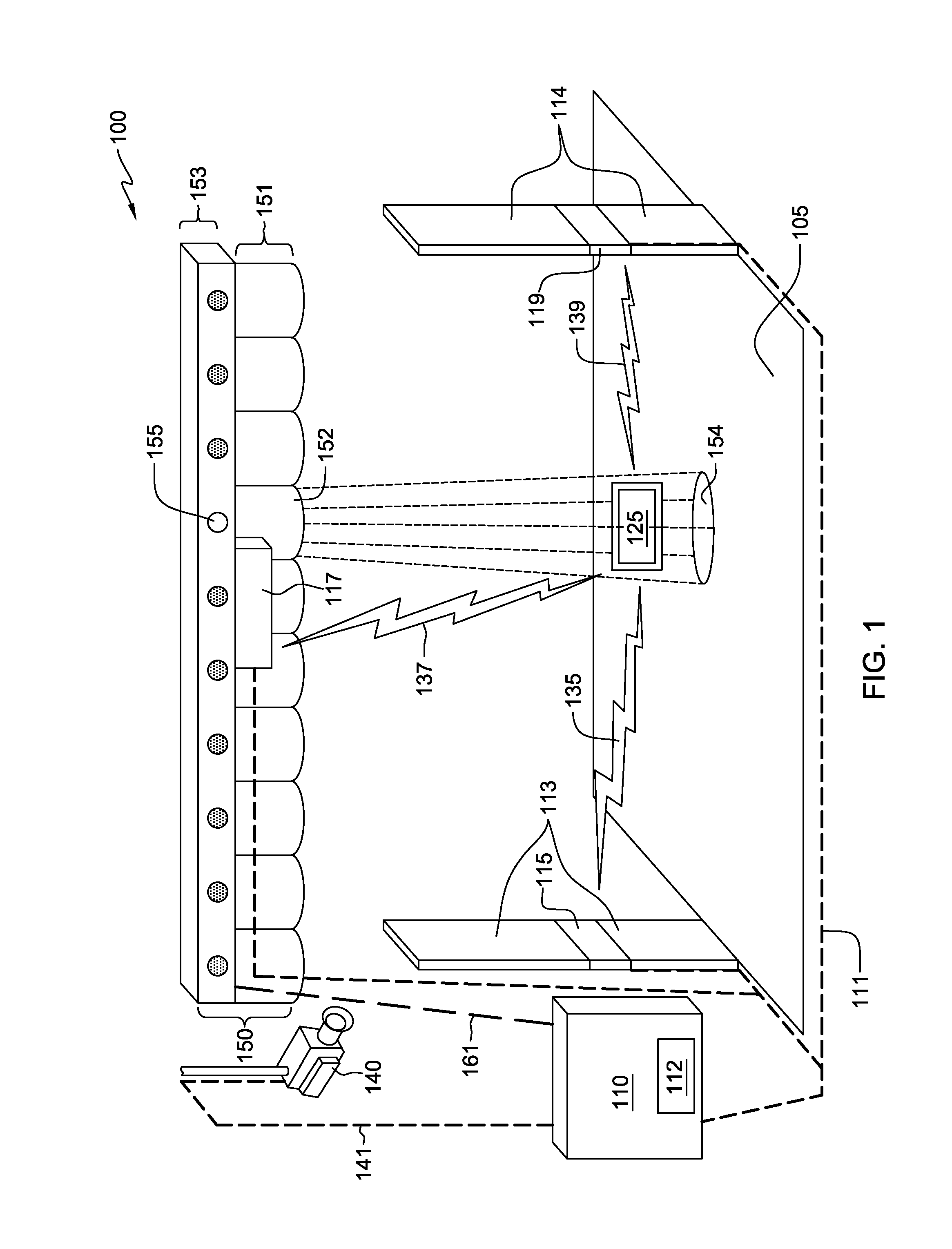
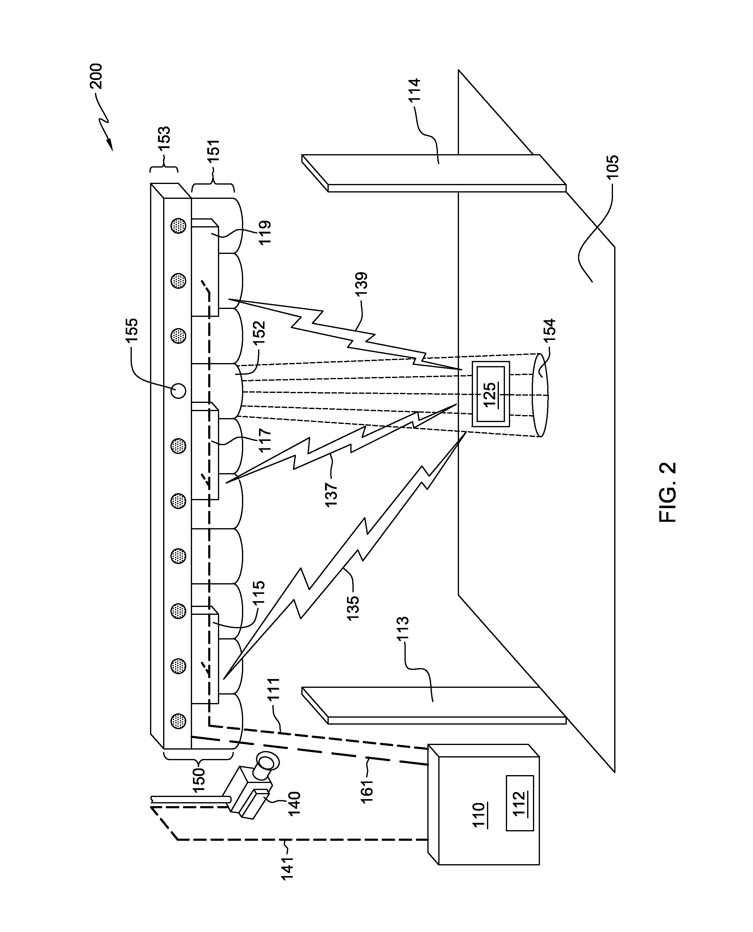
[0034]FIG. 2 is a block diagram, 200, illustrating a component layout for a detection system, 200, in accordance with the present invention. In FIG. 2, RFID detector 115, 117, and 119 are integral with illuminating device 150. Such a configuration can provide a simplified installation of the detection system. In certain embodiments, multiple illuminating device 150 with integral RFID detector 115, 117, and 119 can be employed to monitor an extended surface 105. For example, a store has two such illuminating device 150. The first illuminating device 150 is located on the inside of a given doorway and the second is located on the outside of that doorway. In another example, such illuminating devices 150 are placed at the various pathway intersections of a shopping mall, thereby forming arches under which potential customers must pass. Such a configuration can provide multiple venues with additional security.
third embodiment
[0035]FIG. 3 is a block diagram, 300, illustrating a component layout for a detection system, 300, in accordance with the present invention. In FIG. 3, RFID detector 115, 117, and 119 are integral with illuminating device 150. However, unlike the previous embodiments, surface 105 has been replaced with a grid of light emitting tiles designated indicating tiles 166 and 168. Indicating tiles 166 and 168 are connected to computing device 110 using grid connection 162. Grid connection 162 is, in general, any connection that is capable of passing signals, e.g., data to activate the light emitting tiles, from computing device 110 to indicating tiles 166 and 168.
[0036]As with indicator lights 153 of illuminating device 150 of FIGS. 1 and 2, the light emitting tiles are activated by triangulation program 112 to indicate a general location of a point of origin of a signal. When activated, a given light emitting tile illuminates to provide a general location of a point of origin of a signal. ...
PUM
 Abstract
Description
Claims
Application Information