Silicon solar cell module using conductive npaste as electrode and method for manufacturing same

a solar cell and silicon substrate technology, applied in the direction of non-conductive materials with dispersed conductive materials, semiconductor devices, pv power plants, etc., can solve the problems of poor electrical/mechanical contact of aluminum rear electrodes with metal ribbons, expensive materials that need to be replaced with inexpensive materials, and high cost of silicon solar cells, so as to reduce power, reduce production costs, and reduce the effect of electric curren

Inactive Publication Date: 2015-01-01
GENS ENG
View PDF6 Cites 15 Cited by
  • Summary
  • Abstract
  • Description
  • Claims
  • Application Information

AI Technical Summary

Benefits of technology

[0012]The present invention is directed to a silicon solar cell module comprising electrodes formed from conductive paste. In the present invention, front electrode finger lines and bus bars are separately formed. Specifically, front electrode finger lines are formed by printing a silver paste and calcining the printed paste at high temperature, and front and rear electrode bus bars are formed from a low-temperature inexpensive conductive paste, which includes a curing agent having reducing power and a buffer, in place of an expensive conductive paste, thereby reducing the production cost. Front electrode bas bars formed from a conductive paste according to the present invention do not come into contact with a silicon substrate, and thus the area of contact between the silicon substrate and the front electrode is reduced. Accordingly, the decrease in electric current caused by the recombination of electrons and holes resulting from this contact is inhibited, thereby increasing the photovoltaic conversion efficiency of the solar cell. In addition, when the conductive paste according to the present invention is used, front and rear bus bars can be calcined at low temperatures, and thus the occurrence of cracks in the silicon substrate can be reduced, thereby preventing a decrease in the photovoltaic conversion efficiency of the silicon solar cell and increasing the yield of the silicon solar cell.

Problems solved by technology

However, silicon solar cells include expensive silicon substrates and expensive silver and aluminum pastes.
Thus, in order to lower the price of silicon solar cells to achieve grid parity, the expensive materials are required to be replaced with inexpensive materials.
The aluminum rear electrode may have poor electrical / mechanical contact with a metal ribbon that provides a connection between cells, due to the oxidation of its surface.
Silver that is used in the front electrode and rear electrode bus bars of a silicon solar cell is an expensive rare metal.
1) The resistivity of the metal paste is as low as that of a high temperature silver paste, so that the metal paste does not reduce the solar cell conversion efficiency.
2) The metal paste should be easily soldered to a metal ribbon that provides a connection between cells, so that it is electrically or mechanically easily connected with the metal ribbon.
3) Because a solar cell module should be used for 20 years or more in the open air, the metal paste should not undergo oxidative corrosion when it is used in this environment for a long period of time.
This oxide film is a non-conductive, and thus has a problem in that it interferes with the electrical or mechanical connection between metal particles in the paste and between the front and rear electrode bus bars and the metal ribbon.
Moreover, because the metal powder is surrounded by the polymer of the resin and strongly bonded with the resin, it is not easily soldered to the metal ribbon.
Particularly, when the metal paste composed of copper powder is exposed to air or moisture for a long period of time, it can be oxidized (corroded) to increase the electrical resistance of the electrode to thereby reduce the light conversion efficiency of the solar cell module.
However, the above patent publication does not describe that finger lines and bus lines comprise different components.
However, it does not recognize the effect of the difference in the paste component between the finger electrode and the bus bar on processes or costs.

Method used


Image

  • Silicon solar cell module using conductive npaste as electrode and method for manufacturing same
  • Silicon solar cell module using conductive npaste as electrode and method for manufacturing same
  • Silicon solar cell module using conductive npaste as electrode and method for manufacturing same

Examples


example 1

[0057]The silicon solar cell module according to the present invention was fabricated by the following process.

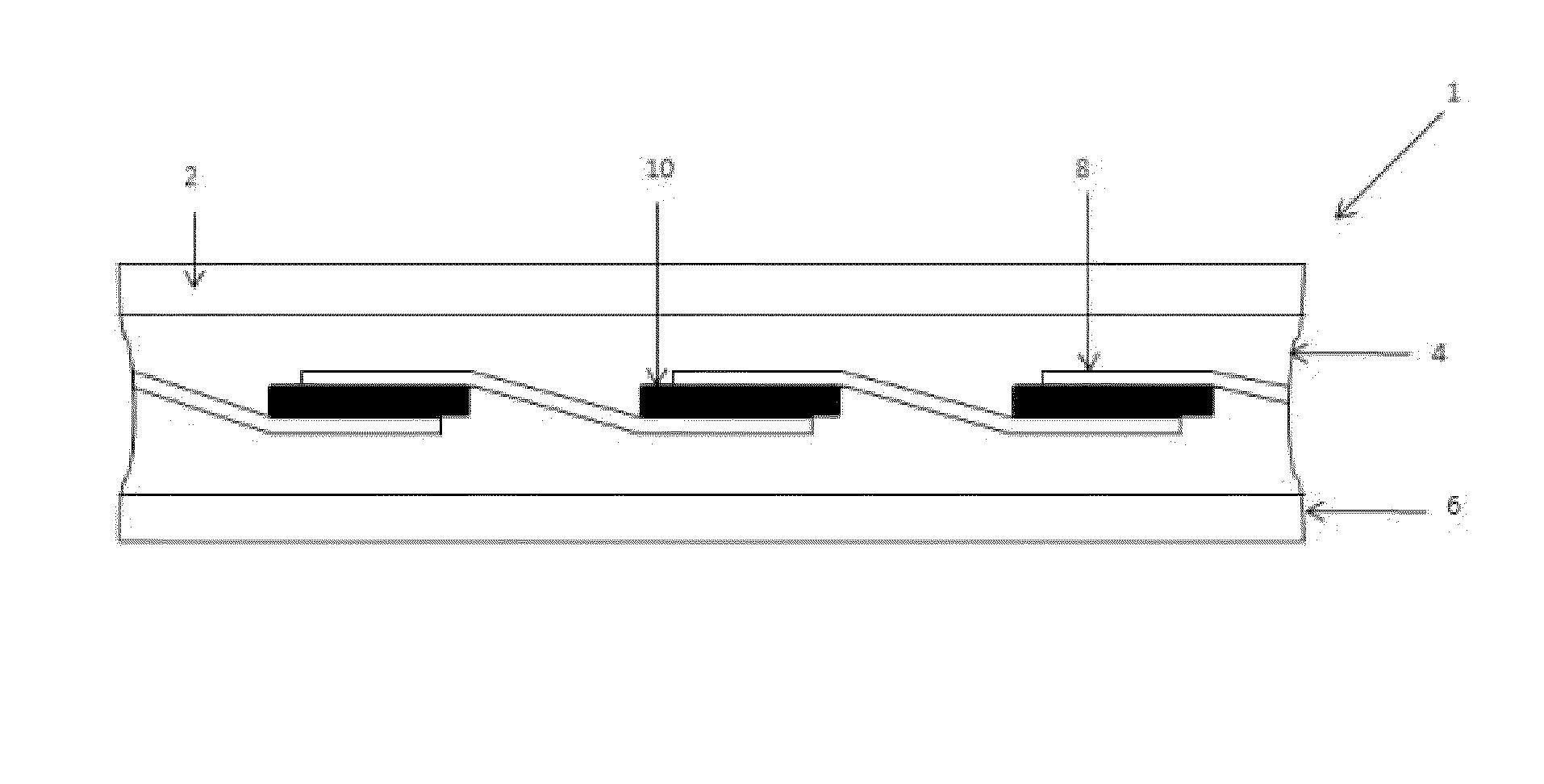
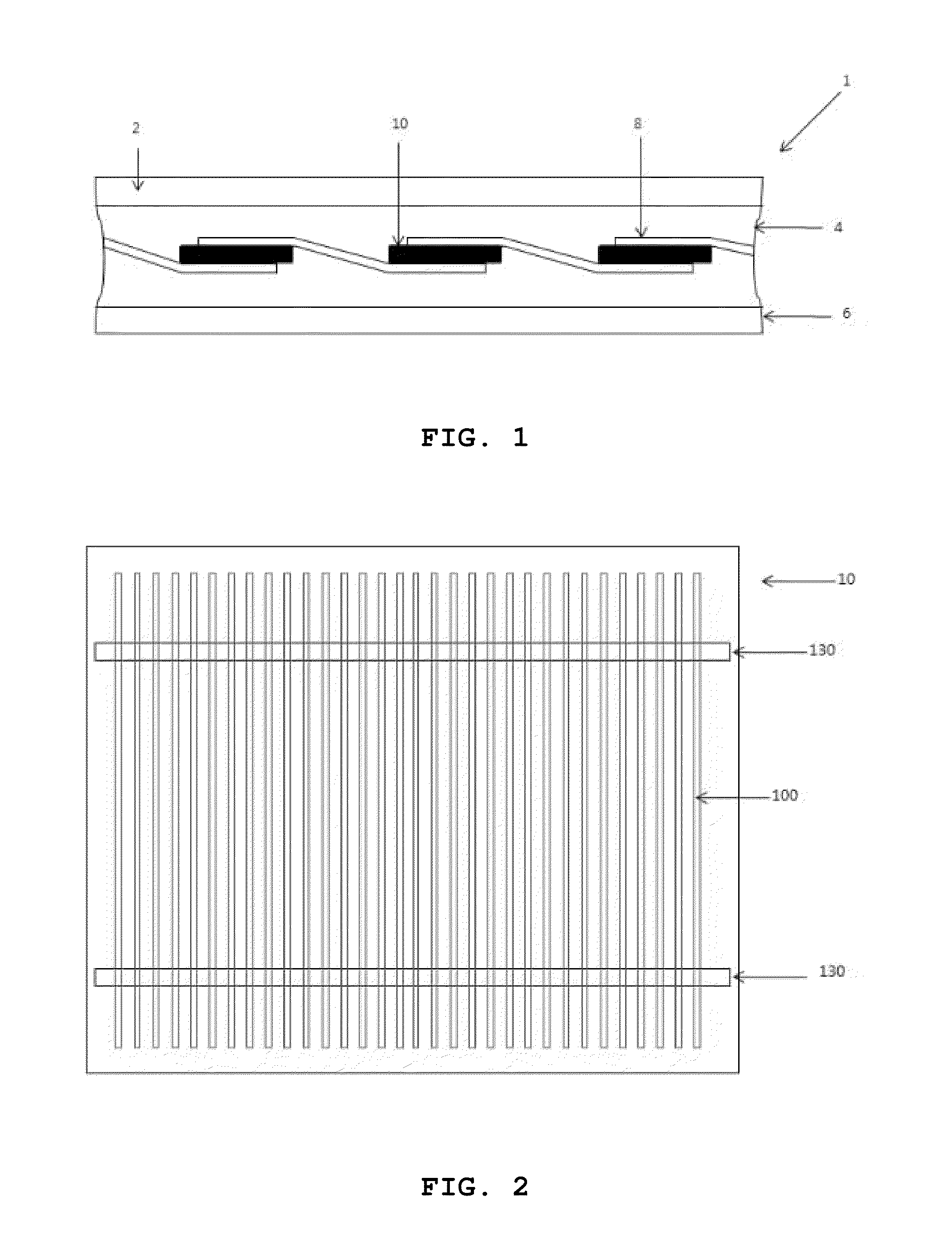
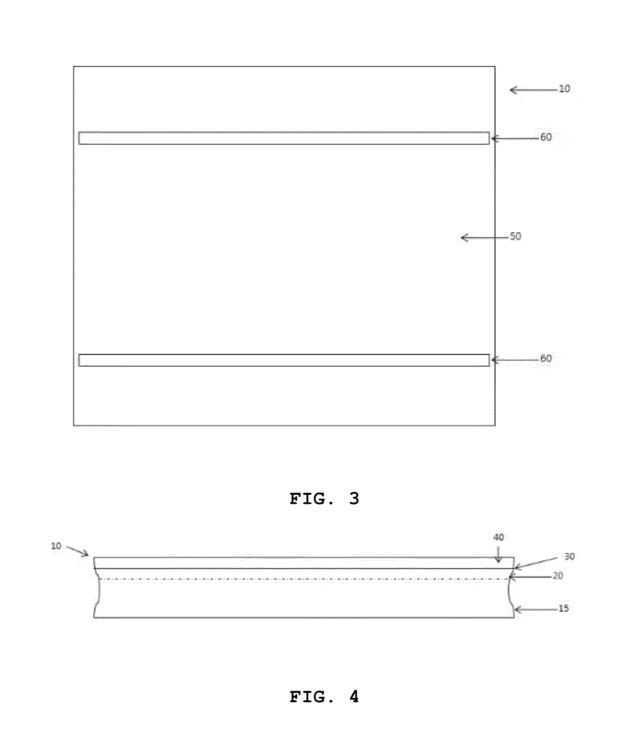
[0058]To fabricate the silicon solar cell, a p-type single-crystal silicon substrate (165×165 mm; thickness: 180 μm) was used. POCl3 was thermally diffused into the front surface of the silicon substrate to form an n-type layer, thereby forming a p-n junction in the silicon substrate. On the n-type layer, a silicon nitride layer was deposited to form an antireflective layer. To form a front electrode on the antireflective layer of the silicon substrate, a high-temperature silver paste was screen-printed on the antireflective layer to form finger lines having a width of 100 μm. An aluminum paste was applied to the entire rear surface of the silicon substrate. The electrode pastes on the front and rear surfaces were calcined at a temperature of 910° C. During this calcining process, the silver paste of the front electrode penetrated through the antireflective layer so as to b...


PUM


Abstract

The present invention relates to a silicon solar cell module comprising electrodes formed from conductive paste. In the invention, front electrode finger lines and front electrode bus bars are separately formed. The front electrode finger lines are formed by printing a silver paste and calcining the printed silver paste at high temperature, and rear electrode bus bars and front electrode bus bars are formed from an inexpensive lower-temperature conductive paste including a buffer and a curing agent having reducing power, whereby the expensive silver paste is replaced with the inexpensive low-temperature conductive paste, thereby reducing the production cost. Because the front electrode bus bars formed from the conductive paste do not come into contact with the silicon substrate, the area of contact between the silicon substrate and the front electrode is reduced, and thus the decrease in electric current caused by the recombination of electrons and holes resulting from this contact is inhibited, thereby increasing the photovoltaic conversion efficiency of the cell. Also, when the conductive paste is used, the rear electrode and front electrode bus bars are calcined at low temperature, and thus the occurrence of cracks in the silicon substrate is reduced, thereby preventing a decrease in the photovoltaic conversion efficiency of the silicon solar cell and increasing the yield of the cell.

Description

TECHNICAL FIELD[0001]The present invention relates to a silicon solar cell module, and more particularly, to a silicon solar cell module comprising electrodes formed from conductive paste.BACKGROUND ART[0002]In recent years, due to serious issues such as the imminent exhaustion of fossil fuels, global warming caused by carbon dioxide emissions resulting from the use of fossil fuels, the accident of nuclear power plants, and radioactive contamination caused by nuclear waste, the development of next-generation clean energy sources has been of increasing importance. Among them, solar power generation systems use infinite resources and are semi-permanent, and thus are receiving as a next-generation energy source. Solar cells that are currently used for solar power generation include crystalline silicon solar cells, thin film silicon solar cells, CdTe solar cells, CIGS solar cells, dye-sensitized solar cells, organic solar cells, and concentrated solar cells. Currently, silicon solar cel...

Claims


Application Information

Patent Timeline
Patent Type & Authority Applications(United States)
IPC IPC(8): H01L31/05H01L31/18H01L31/048H01L31/042H01L31/0224
CPCH01L31/022425H01L31/18H01L31/048Y02E10/50Y02E10/52H01L31/0201H01L31/1804H01B1/22H01L31/0504Y02E10/547H01L31/0224H01L31/042H01L31/05
Inventor CHO, SOON, HAENG
Owner GENS ENG
Why Eureka
Try Eureka