Lubricated elastically biased stretch hoses

a technology of elastically biased stretch hoses and lubricating pads, which is applied in the direction of flexible pipes, mechanical equipment, textiles and paper, etc., can solve the problems of inner elastic tube being stretched beyond its limit in that section, inner elastic tube being stowed in place within the reinforcement cover, inner elastic tube being stowed in place, etc., to prevent localized over-stretching and breakage of inner elastic tubes, reduce friction between the two surfaces, and reduce wear

Active Publication Date: 2015-01-08
RAGNER TECH CORP
View PDF10 Cites 47 Cited by
  • Summary
  • Abstract
  • Description
  • Claims
  • Application Information

AI Technical Summary

Benefits of technology

[0012]Accordingly, several objects and advantages which can be achieved using various aspects of the disclosed technology include:
[0023]j) To provide an elastically retractable pressure hose comprising an outer reinforcement cover and an inner elastic tube, wherein the inner elastic tube defines a bonding ridge (e.g. convoluted ridge, parallel rings, short ridge sections, etc.) protruding from its exterior surface, wherein the bonding ridge can frictionally interact with the interior wall of the outer cover to stabilize the inner elastic tube within the reinforcement cover and prevent localized over-stretching and breakage of the inner elastic tube. Wherein a lubricant is applied to the interior surface of the outer reinforcement cover and / or to the exterior surface of the inner elastic tube to reduce friction between the two surfaces.
[0040]z) The elastic retractable pressure hose in items e) through w) wherein the lubricant reduces chafing and wear on the exterior surface of the inner elastic tube.

Problems solved by technology

First, an inner elastic tube can chafe against the interior wall of a woven reinforcement cover (outer cover) which will eventually cause it to rupture.
Second, an inner elastic tube can experience localized stretching that is beyond its elastic limit and which thereby can cause the inner tube to fail.
One problem with existing designs is that an inner elastic tube can get out of position within its reinforcement cover and be broken because of binding.
The problem occurs when prior art inner elastic hose 24 (inner elastic tube) binds against reinforcement outer cover 26 and is stretched excessively along one section of the inner elastic tube.
If too much reinforcement cover material exists between these two friction points the inner elastic tube can be stretched beyond its limit in that section and burst.

Method used


Image

  • Lubricated elastically biased stretch hoses
  • Lubricated elastically biased stretch hoses
  • Lubricated elastically biased stretch hoses

Examples


Embodiment Construction

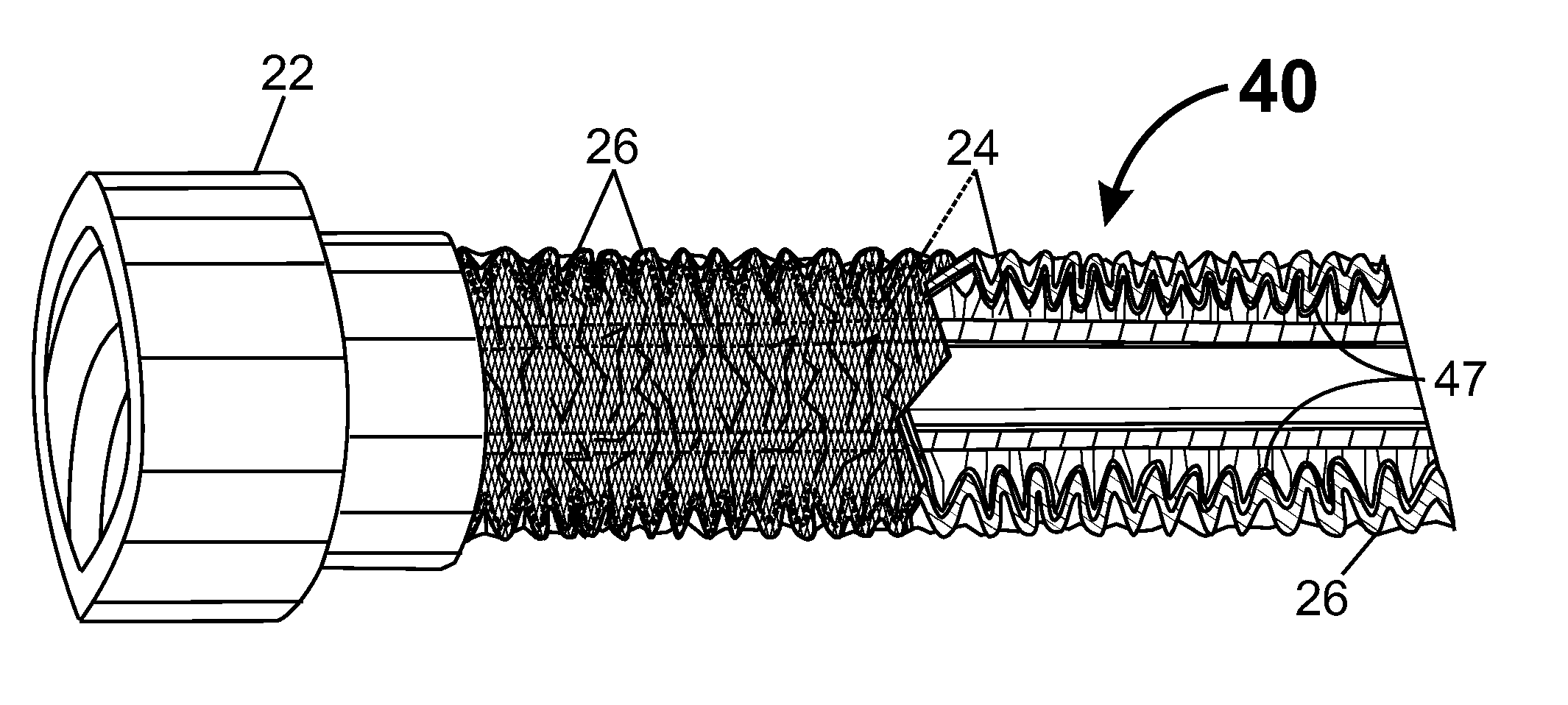
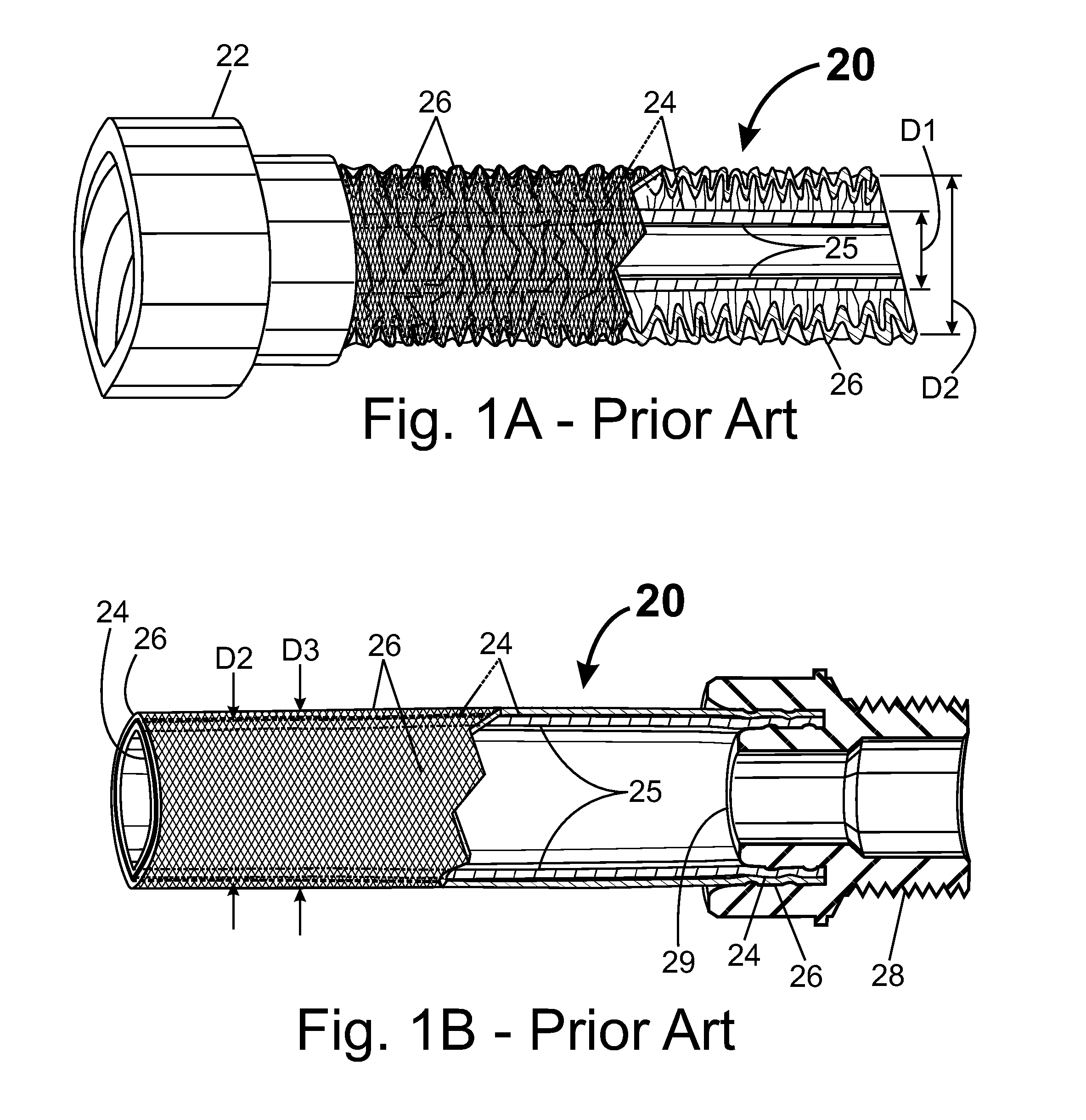
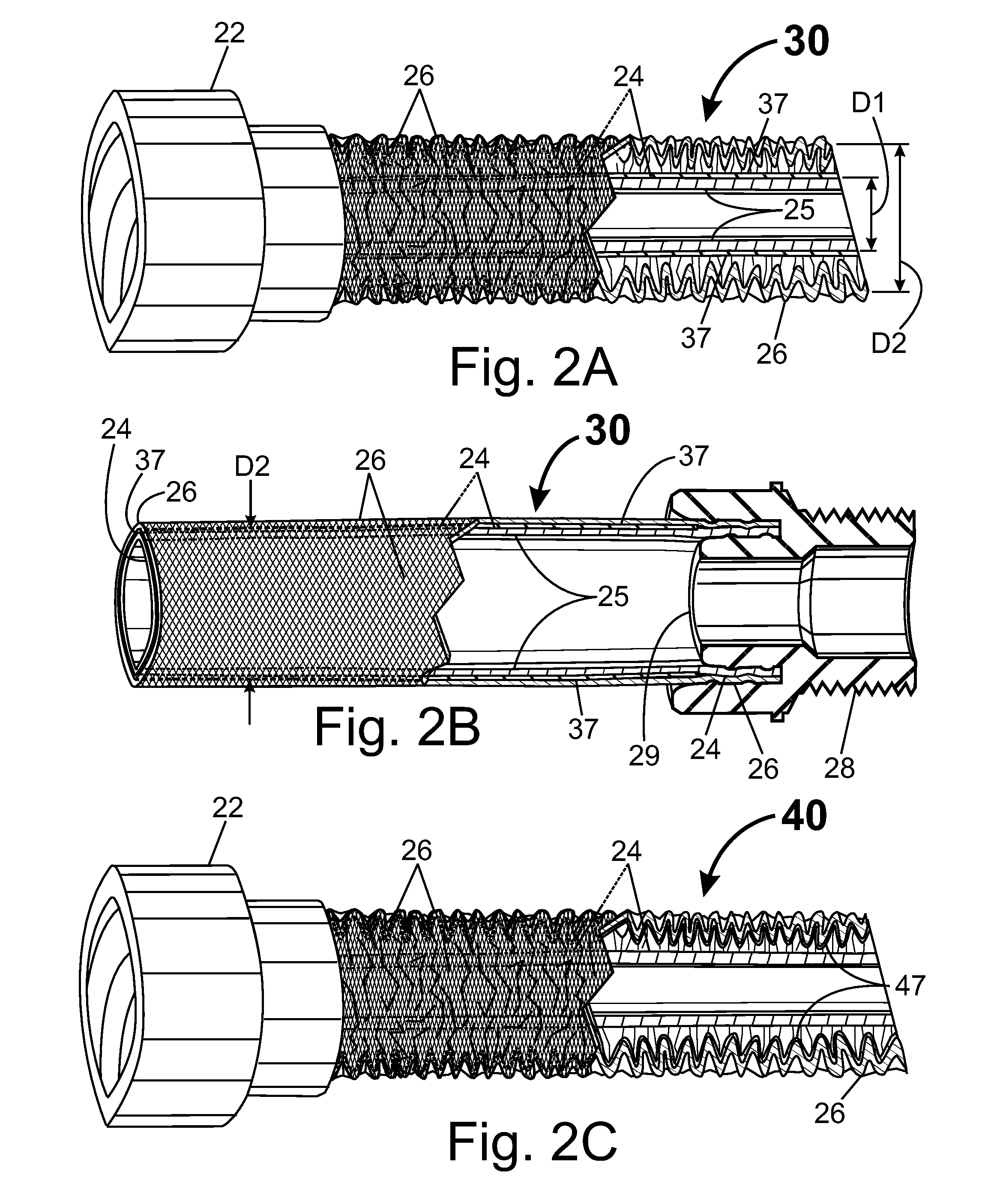
[0056]In FIG. 1A-B, we see a perspective section view of a prior art retractable stretch hose 20 (retractable pressure hose) similar to the “X-hose” produced by National Express. FIG. 1A shows hose 20 in its relaxed state (depressurized), while FIG. 1B shows hose 20 in its pressurized operational state. Retractable hose 20 comprises an inner elastic hose 24 (inner elastic tube), a woven reinforcement outer cover 26, an inlet connector 22, and an outlet connector 28. Outer cover 26 can comprise a tube-shaped woven reinforcement that is composed of high-strength fibers, and designed to support the pressure conducted into inner elastic tube 24. Outlet connector 28 comprises a flow restriction ridge 29 to generate pressure within interior channel 25 of elastic tube 24. Inner elastic tube 24 extends through reinforcement outer cover 26 where the natural length of inner elastic tube 24 is about one-third the natural length of woven outer cover 26. Inner elastic tube 24 has an outside diam...


PUM


Abstract

A retractable pressure hose can be created which comprises an inlet connector, an outlet connector, an inner elastic tube, an outer cover, and a lubricant disposed to reducing chafing between the inner elastic tube and the outer cover. In such a hose, the lubricant can comprise a solid lubricant such as paraffin wax or other slippery solids, a liquid lubricant such as olive oil or other slippery liquids, or a combination of solid and/or liquid lubricants.

Description

CROSS REFERENCE TO RELATED APPLICATIONS[0001]The present application is:[0002]a) a continuation in part of U.S. application Ser. No. 14 / 075,963 filed on Nov. 8, 2013, which is itself a non-provisional of U.S. provisional patent applications 61 / 724,890, 61 / 732,291 and 61 / 856,054, filed, respectively, on Nov. 9, 2012, Dec. 1, 2012, and Jul. 19, 2013;[0003]b) a continuation in part of U.S. application Ser. No. 14 / 455,461 filed on Aug. 8, 2014, which is itself a non-provisional of U.S. provisional patent application 61 / 864,555, filed on Aug. 10, 2013;[0004]c) a non-provisional of provisional application 61 / 856,054 filed on Jul. 19, 2013; and[0005]d) a non-provisional of provisional application 62 / 039,913 filed on Aug. 21, 2014;of which applications, application Ser. Nos. 14 / 075,963, 14 / 455,461, and provisional applications 61 / 724,890, 61 / 732,291, 61 / 856,054 and 62 / 039,913 are hereby incorporated by reference in their entirety, including any figures, tables, equations or drawings.BACKGRO...

Claims


Application Information

Patent Timeline
Patent Type & Authority Applications(United States)
IPC IPC(8): F16L11/118
CPCF16L11/118D03D3/02D03D3/06
Inventor RAGNER, GARY DEAN
Owner RAGNER TECH CORP
Why Eureka
Try Eureka