Projection type image display device

a projection type, image display technology, applied in the direction of instruments, cathode-ray tube indicators, vehicle components, etc., can solve the problems of uneven brightness of the image at different parts observed by the viewer of the image (i.e., the driver of the vehicle), and the projection type image display device cannot grasp the physical relationship between the projection type image display device and the image display surface, so as to prevent uneven brightness of the two areas, less recognizable, and prevent uneven brightness of the reflected image ligh

Inactive Publication Date: 2015-01-08
DENSO CORP
View PDF8 Cites 81 Cited by
  • Summary
  • Abstract
  • Description
  • Claims
  • Application Information

AI Technical Summary

Benefits of technology

[0012]However, according to the above-described disclosure, the image projection device is arranged to control the retro-reflective components of the reflected image light from the first and second areas respectively to direct them away from the driver's seat. Therefore, the diffusive component of the reflected image light and not the retro-reflective component of the reflected image light enter into the driver's eye and are thus recognized by the driver. Further, a ratio of the retro-reflective component in the reflected image light from the first area is greater than a ratio of the retro-reflective component in the reflected

Problems solved by technology

More specifically, the projection type image display device which projects light onto the three-dimensional surface for the display of the image cannot grasp the physical relationship between the projection type image display device and the image display surface even when the intensity of the reflected light is measured by the light intensity sensor of the patent document 1.
That is, the projection type image display device of the patent document 1 is suitable only for displaying an image on the tw

Method used


Image

  • Projection type image display device
  • Projection type image display device
  • Projection type image display device

Examples


first embodiment

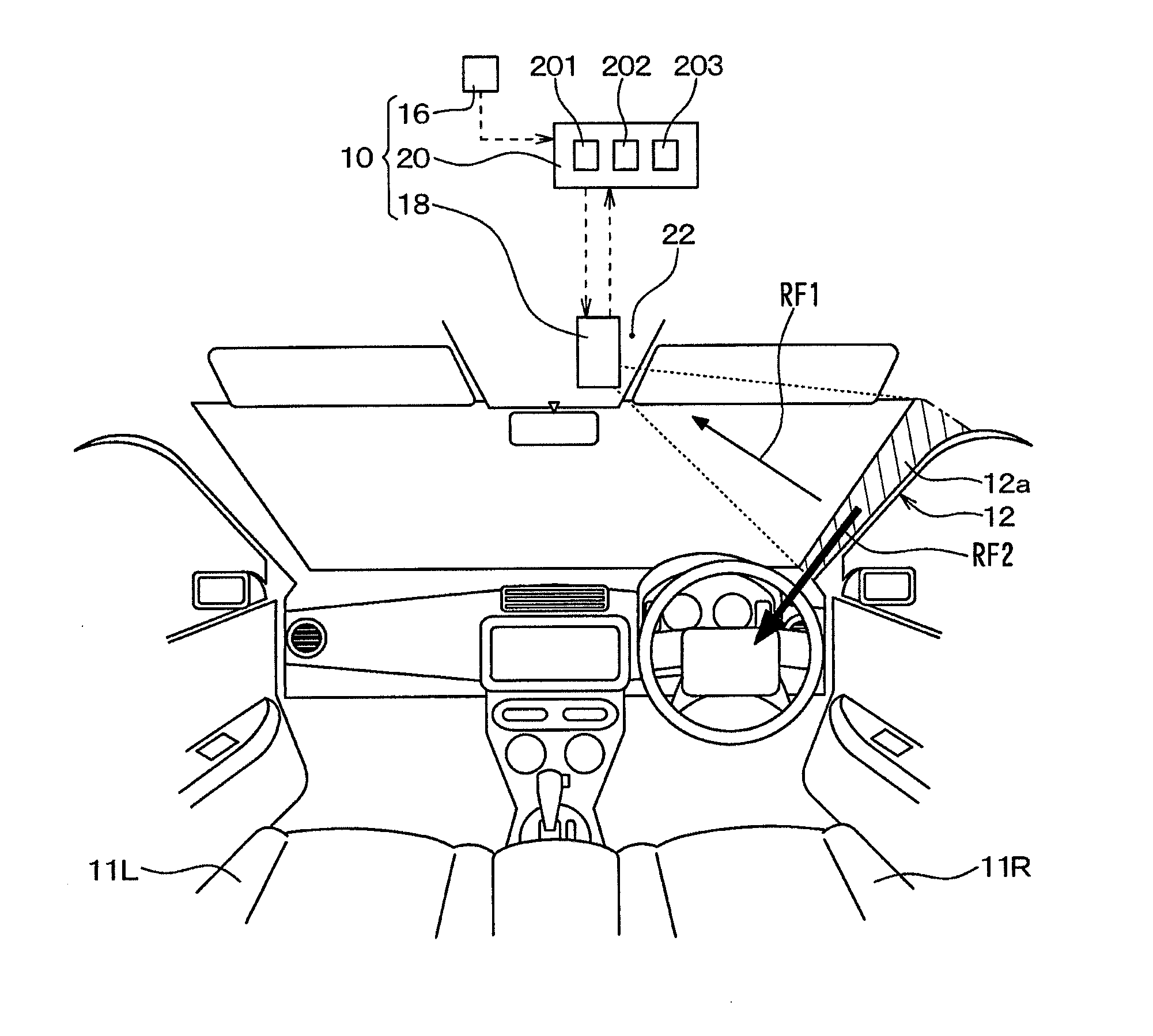
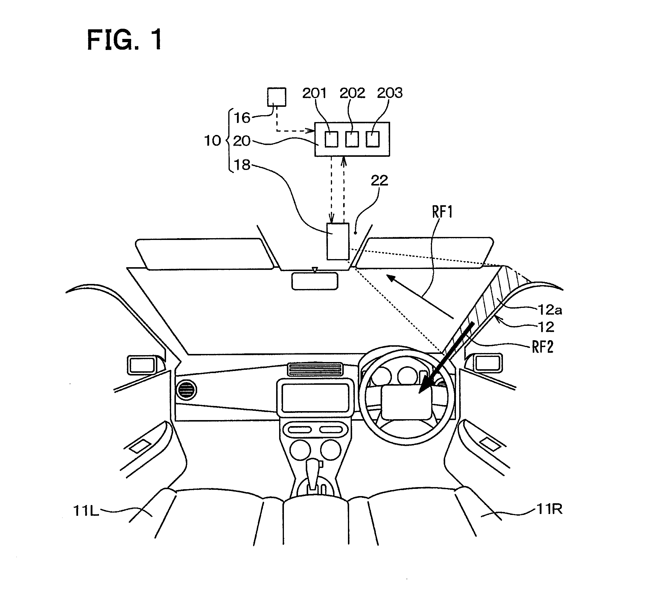
[0029]FIG. 1 shows an illustrated configuration of a projection type image display device 10 in the first embodiment, together with a front view from an inside of a vehicle compartment in the first embodiment of the present disclosure. This projection type image display device 10 is a display device for vehicles, and it is used, for example, to perform an optical camouflage in a vehicle compartment. More specifically, the projection type image display device 10 may be used to optically eliminate a dead angle (i.e., causing a blind spot) in a view of a driver, which is caused by an A-pillar 12 disposed on a driver's side of a windshield (i.e., on a driver's seat 11R side), by projecting an outside view image onto an inside surface 12a of the A-pillar 12, i.e., onto an A-pillar surface 12a outside view image projected thereon is thus taken as a matching image of a dead angle caused by the A-pillar 12 in a view of the driver. The front pillar 12, i.e., the A-pillar 12, corresponds to a...

second embodiment

[0062]The second embodiment of the present disclosure is described in the following. The description of the present embodiment focuses on a different point from the above-mentioned first embodiment, and the same description as the first embodiment will not be repeated.

[0063]FIG. 4 shows an outline configuration of the projection type image display device 10 of the present embodiment, together with a front view from an inside of a vehicle compartment in the first embodiment of the present disclosure. In the first embodiment described above, the projection range of the image light from the image projection device 18 is adjusted to the display target range, not by changing the position and / or angle of the image projection device 18 relative to the ceiling 22, but by adjusting the rotation range of the X / Y-axis galvanometers in the image projection device 18.

[0064]On the other hand, in the present embodiment, a projection range RGpj of the image projection device 18 is adjusted to the d...

second embodiments

Modifications of First and Second Embodiments

[0070](1) In each of the above-mentioned embodiments, the projection type image display device 10 is used in order to perform the optical camouflage in a vehicle compartment, but the projection type image display device 10 may be used for the other purposes other than the optical camouflage.

[0071]For example, the projection type image display device 10 may display, by projecting the image light, an image about a function or an operation method of an operation switch or the like in the vehicle compartment on or around such operation switch, for guiding the operation of the operation switch by the vehicle occupant. If, for example, the operation switch is an air-conditioner switch, an image showing an operation direction of the air-conditioner switch is displayed on a surface of the air-conditioner switch.

[0072]In case that the projection type image display device 10 is not used for the optical camouflage, the camera 16 for imaging the outs...


PUM


Abstract

A projection type image display device includes a processor having a measuring part for performing a three-dimensional measurement of an A-pillar and a projection range controller for controlling a projection range of an image light, which is matched to an A-pillar surface based on a result of the three-dimensional measurement. Thus, the projection of an image onto the A-pillar surface by the projection type image display device is easily performed regardless of whether the A-pillar surface is a two-dimensional flat surface or a three-dimensional surface. The projection type image display device also directs a retro-reflective component in a reflected image light away from a driver's seat based on a positioning of an image projection device. Speckled uneven image brightness on an image display surface is thereby prevented.

Description

CROSS REFERENCE TO RELATED APPLICATION[0001]The present application is based on and claims the benefit of priority of Japanese Patent Applications No. 2013-138776 and No. 2013-138777, both filed on Jul. 2, 2013, the disclosures of which are incorporated herein by reference.TECHNICAL FIELD[0002]The present disclosure generally relates to a projection type image display device for displaying an image by projecting light onto an object surface of a vehicle compartment.BACKGROUND INFORMATION[0003]A patent document 1 (i.e., Japanese Patent No. 3761550) discloses a projection type image display device which displays an image by projecting light onto an object surface. In patent document 1, the projection type image display device displays the image by projecting light onto the object surface or onto a projection face. The projection type image display device further includes a light intensity sensor for measuring the intensity of a reflected light by receiving the reflected light that is ...

Claims


Application Information

Patent Timeline
IPC IPC(8): B60R1/00
CPCB60R2300/205B60R1/00B60R2300/202
Inventor HANEDA, NARIHIROSAKAI, MAKOTO
Owner DENSO CORP
Why Eureka
Try Eureka