Check patentability & draft patents in minutes with Patsnap Eureka AI!

Electrical connectors and receptacle assemblies having retention inserts

a technology of electrical connectors and receptacle assemblies, which is applied in the direction of electrical apparatus, connection, coupling device connection, etc., can solve the problems of limiting the ability of manufacturers to design electrical connectors with improved performance, limiting the ability of the housing to be molded around the mating contact, and having certain limitations

Active Publication Date: 2015-01-08
TYCO ELECTRONICS LOGISTICS AG (CH)
View PDF2 Cites 0 Cited by
  • Summary
  • Abstract
  • Description
  • Claims
  • Application Information

AI Technical Summary

Benefits of technology

This patent describes an electrical connector that includes a housing with a contact cavity for holding electrical contacts. The housing has side openings that allow a mating connector to be inserted. The electrical contacts are held in place by a retention insert with fingers that engage with the contacts. The connector can be mounted to a circuit board using screws or solder. The technical effect of this invention is to provide a secure and reliable electrical connection between a mating connector and a circuit board.

Problems solved by technology

However, such electrical connectors may have certain limitations.
For example, mating contacts that have shapes or dimensions that predispose the mating contacts to deformation may be inadvertently bent when inserted into the hole.
Furthermore, molding the housing around the mating contacts may be costly as compared to other manufacturing methods.
In some cases, the above manufacturing methods may limit a manufacturer's ability to design electrical connectors with improved performance.
But, such a size of the retention segments may negatively affect the electrical characteristics of the mating contacts.
For example, such a size of the retention segments may degrade the integrity of signals transmitted through the mating contacts and / or may cause electrical discontinuities, such as, but not limited to, reflections, impedance differences, electrical stubs, etc.

Method used


Image

  • Electrical connectors and receptacle assemblies having retention inserts
  • Electrical connectors and receptacle assemblies having retention inserts
  • Electrical connectors and receptacle assemblies having retention inserts

Examples


Embodiment Construction

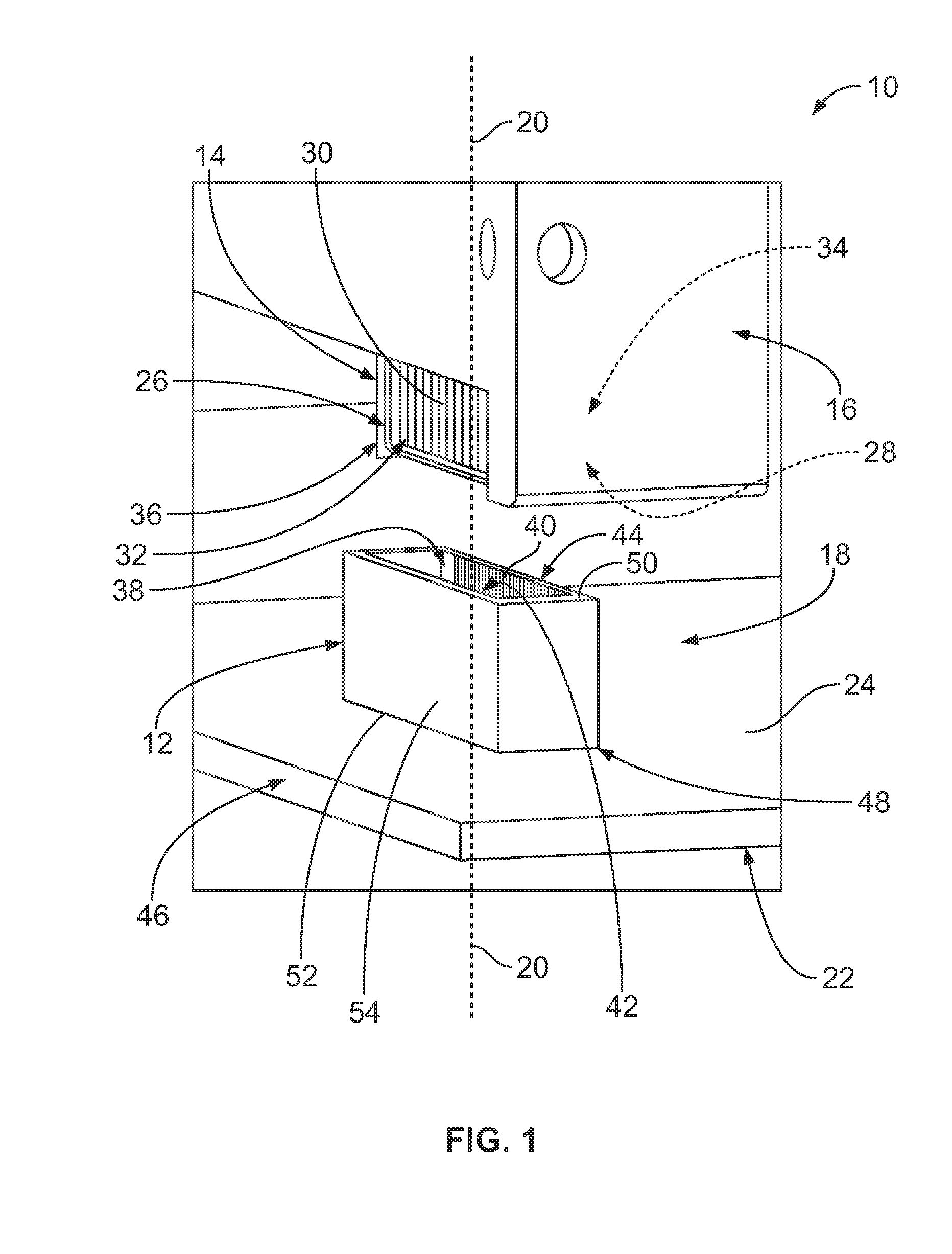
[0017]FIG. 1 is a perspective view of an embodiment of a communication system 10. The communication system 10 includes an electrical connector 12 and a mating connector 14. The communication system 10 includes an electrical component 16 that includes the mating connector 14, and a receptacle assembly 18 that includes the electrical connector 12. The receptacle assembly 18 is configured to communicatively engage the electrical component 16. Specifically, the electrical connector 12 and the mating connector 14 are configured to mate together along a mating axis 20 to electrically connect the electrical component 16 to the receptacle assembly 18.

[0018]As shown in FIG. 1, the receptacle assembly 18 may include a circuit board 22 that includes a board surface 24 having a plurality of electrical contacts (not shown). The electrical contacts of the circuit board 22 may be, for example, contact pads, plated through-holes, and / or the like. The electrical connector 12 is configured to be moun...


PUM


Abstract

An electrical connector includes a housing extending from a mating face to an opposite face, and first and second side walls that extend between the mating face and the opposite face. The housing has a contact cavity that includes opposing sides. The first side wall includes a side opening that extends through the first side wall into communication with the contact cavity. The contact cavity is accessible through the mating face for receiving a mating connector therein. Electrical contacts are held by the housing and arranged in opposing rows that extend along the opposing sides of the contact cavity. A retention insert is received within the side opening. The retention insert includes fingers that extend into the contact cavity and engage in physical contact with corresponding electrical contacts of one of the rows of the electrical contacts to hold the corresponding electrical contacts within the contact cavity.

Description

BACKGROUND OF THE INVENTION[0001]The subject matter described and / or illustrated herein relates generally to electrical connectors, and more particularly, to electrical connectors that are configured to receive and communicatively engage an edge of a mating connector.[0002]Various communication or computing systems use electrical connectors for transmitting data signals between different components of the systems. For example, some electrical connectors may be configured to receive an edge of an electrical component having component contacts located therealong. The electrical connectors may include housing cavities having opposing rows of mating contacts. When the edge is advanced into the housing cavity of the electrical connector, the edge moves between the opposing rows of mating contacts. The component contacts electrically engage the mating contacts in the housing cavity.[0003]Electrical connectors such as those described above may be manufactured by molding a housing with hole...

Claims


Application Information

Patent Timeline
Patent Type & Authority Applications(United States)
IPC IPC(8): H01R13/639
CPCH01R13/639H01R12/725H01R13/4361
Inventor BRIANT, ERIC DAVID
Owner TYCO ELECTRONICS LOGISTICS AG (CH)
Features
  • R&D
  • Intellectual Property
  • Life Sciences
  • Materials
  • Tech Scout
  • Unparalleled Data Quality
  • Higher Quality Content
  • 60% Fewer Hallucinations
Learn More