

Position adjusting system and method
a technology of positioning adjustment and system, applied in the field of positioning adjustment devices, can solve problems such as inadequacies of above-mentioned methods
- Summary
- Abstract
- Description
- Claims
- Application Information
AI Technical Summary
Benefits of technology
Problems solved by technology
Method used
Image

Examples
Embodiment Construction
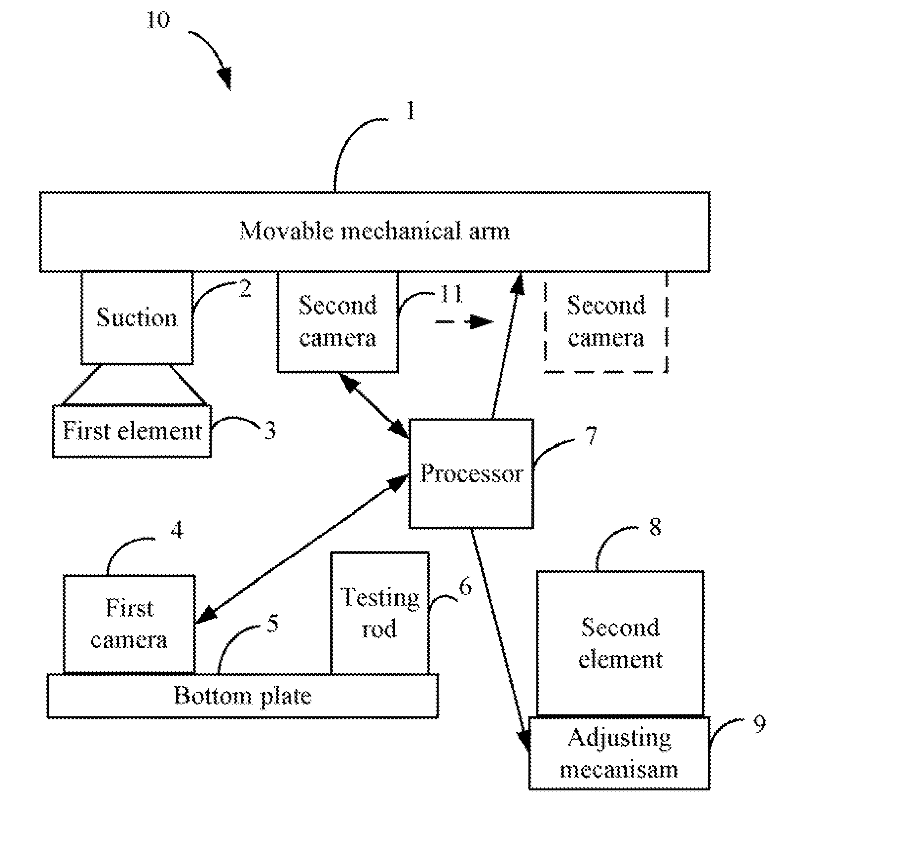
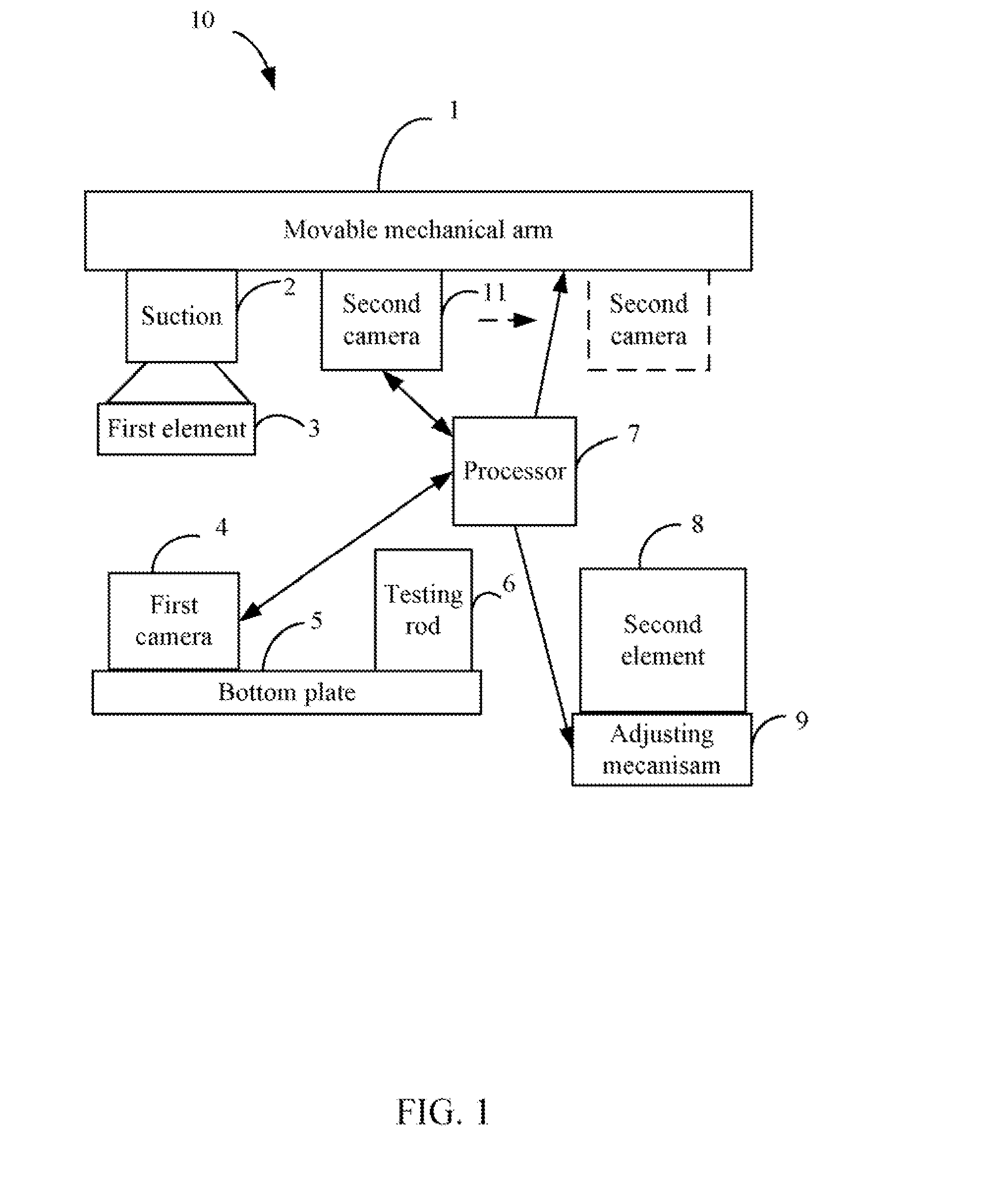
[0016]FIG. 1 shows a position adjusting device 10. The position adjusting device 10 is used to adjust a position of a second element 8 based on a position of a first element 3. The position adjusting device 10 includes a movable mechanical arm 1, a suction 2 fixed on the mechanical arm 1, an adjusting mechanism 9 and a bottom plate 5 placed below the mechanical arm 1, a first camera 4 fixed on the bottom plate 5, a second camera 11 fixed on the mechanical arm 1, and a processor 7. The suction 2 is used to suck the first element 3. The adjusting mechanism 9 is used to support the second element 8.
[0017]The first camera 4 captures a first image of the first element 3 when the first camera 4 is in an enabled state. The second camera 11 captures a second image of the second element 8 when the second camera 11 is in an enabled state. In one embodiment, the first image of the first element 3 in FIG. 1 is defined as a first predetermined image. The second image of the second element 8 in F...
PUM
 Abstract
Description
Claims
Application Information