
Four-direction switch device

a switch device and four-direction technology, applied in the direction of emergency actuators, electrical devices, operation facilitation, etc., can solve problems such as erroneous switches, and achieve the effects of preventing excessive tottering of switch knobs, enhancing durability of pivot projections, and improving durability

Active Publication Date: 2015-01-15
TOYO DENSO +1
View PDF2 Cites 0 Cited by
  • Summary
  • Abstract
  • Description
  • Claims
  • Application Information

AI Technical Summary

Benefits of technology

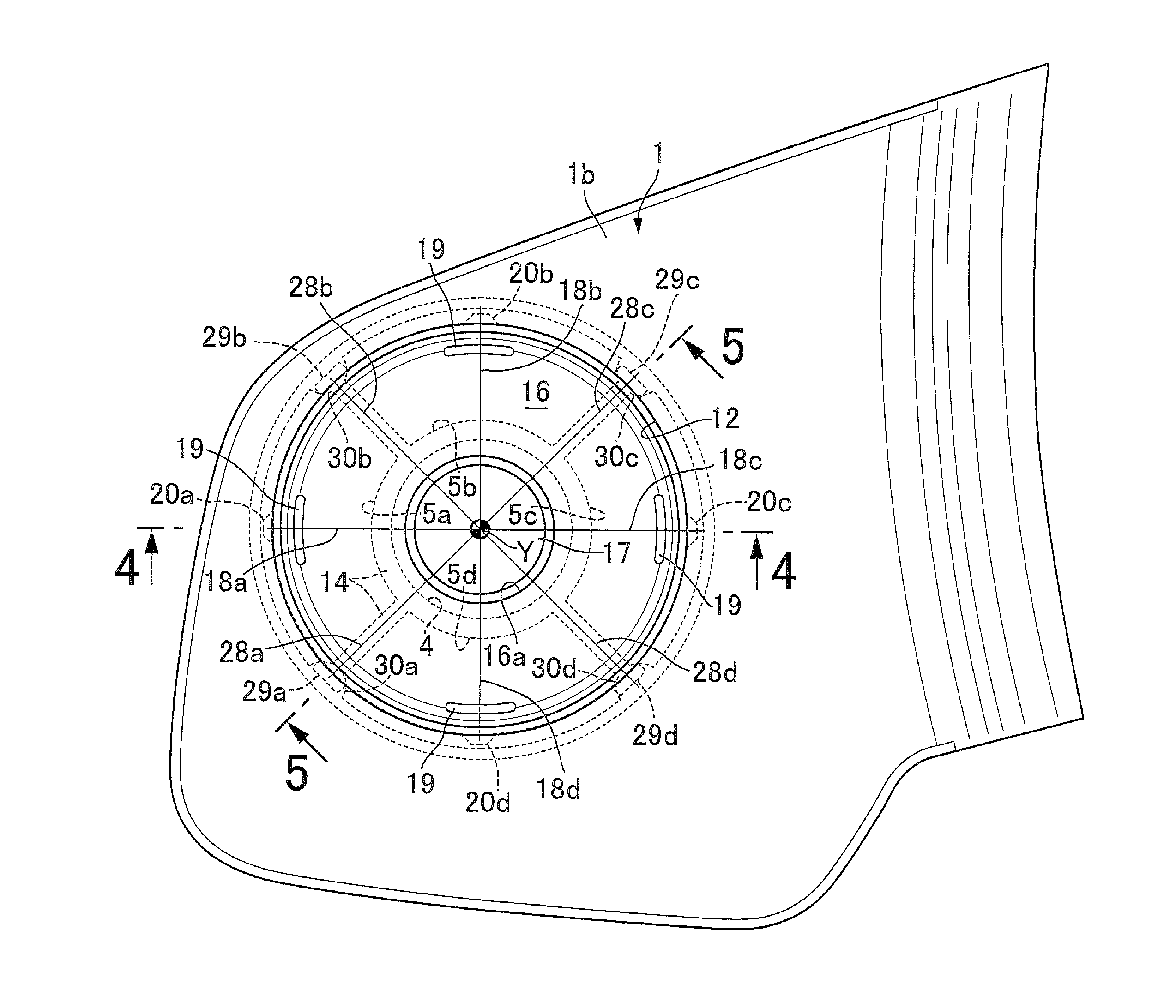
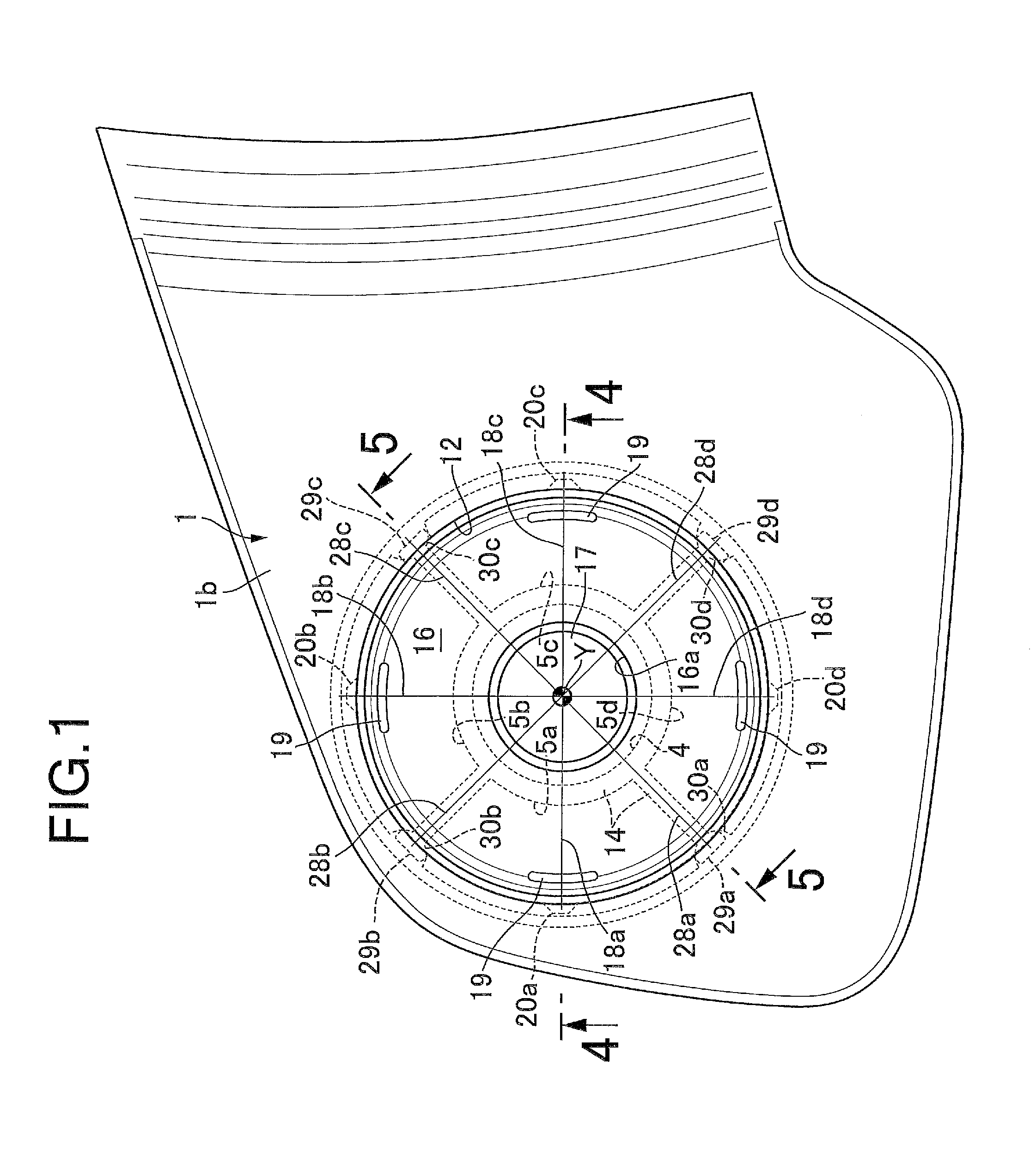
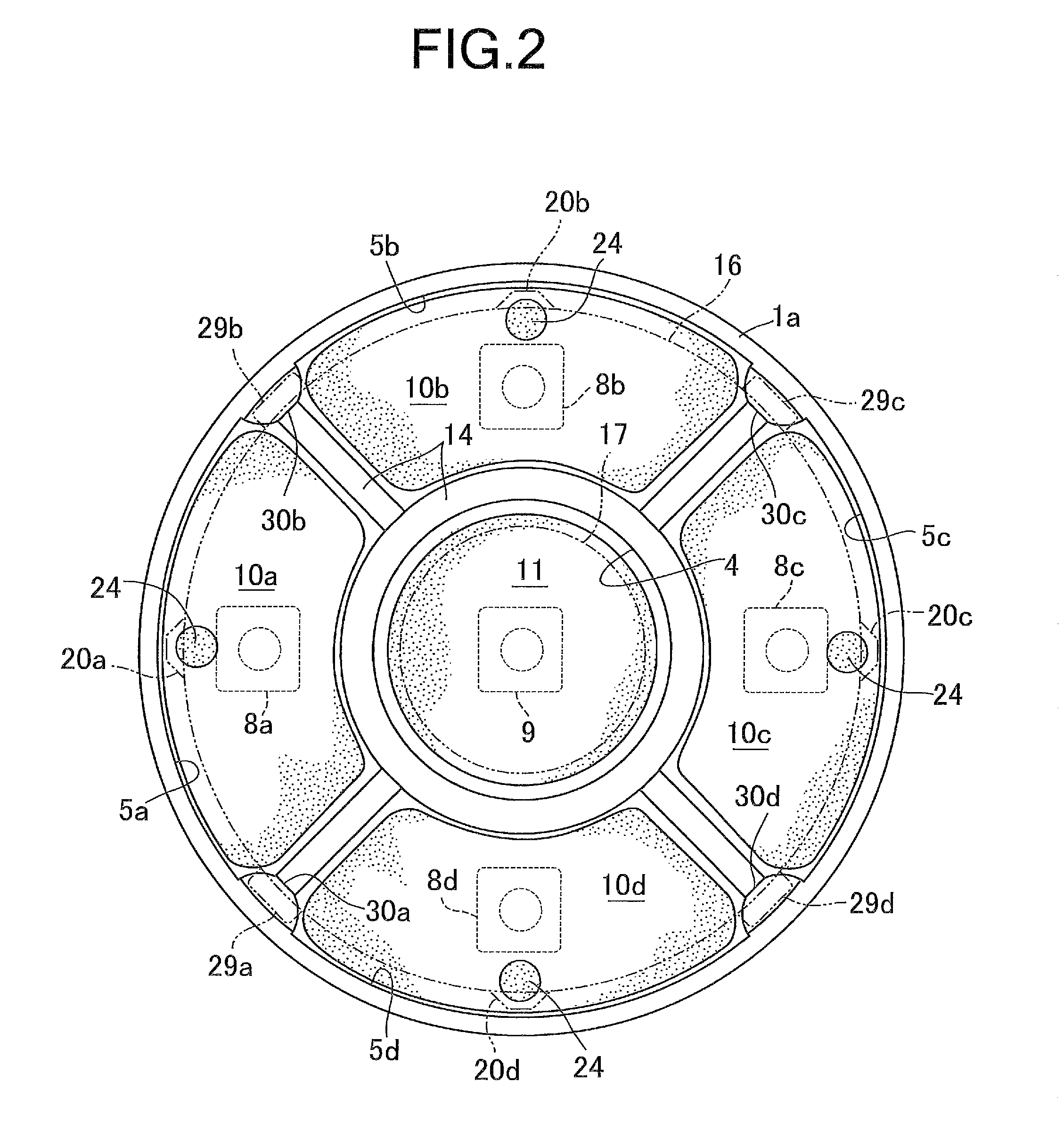
The present invention provides a four-direction switch device that prevents unsteadiness of the switch knob when a switch dead part is pushed, thereby avoiding an unnecessary actuation of a switch. This is achieved by designing the switch knob in a disc shape with first to fourth pivot projections and first to fourth movable stoppers, and the switch case with first to fourth fixed stoppers. When the switch knob is pushed at a switch dead part, the switch knob swings about a straight line connecting a pair of the pivot projections located on the opposite side of the switch dead part with the center axis of the switch knob interposed between the pair of the pivot projections and the switch dead part, but the movable stopper comes into contact with the corresponding fixed stopper and stops the switch knob from swinging any more. This prevents the switch from being actuated due to the tottering motion of the switch knob. Additionally, the pivot projections are arranged on a common straight line, which enhances the durability of the pivot projections.

Problems solved by technology

For this reason, even when the switch knob is stopped from swinging, the switch knob is likely to become unsteady about an axis connecting two points which are one corner and one stopper, and such unsteadiness may actuate a switch erroneously.

Method used


Image

  • Four-direction switch device
  • Four-direction switch device
  • Four-direction switch device

Examples


Embodiment Construction

[0022]Hereinafter, an embodiment of the present invention is described based on the accompanying drawings.

[0023]Firstly, as illustrated in FIGS. 1 to 4, a switch case 1 of a four-direction switch device includes a lower case 1a and an upper case 1b fitted to an outer periphery of the lower case 1a. Multiple locking claws 2 are provided to protrude on the outer peripheral surface of the lower case 1a, and catch holes 3 are provided in a peripheral wall of the upper case 1b. The lower case 1a and the upper case 1b are joined together with the locking claws 2 and the catch holes 3 engaged with each other.

[0024]An inside of the lower case 1a is partitioned, by a partition wall 14 formed integrally with the lower case 1a, into a center switch chamber 4 and first to fourth switch chambers 5a to 5d annularly surrounding the center switch chamber 4. A control circuit substrate 6 is fixed to a lower portion of the lower case 1 a with screws 7. First to fourth switches 8a to 8d respectively a...


PUM


Abstract

In a four-direction switch device, an outer peripheral surface of a disc-shaped switch knob is provided with first to fourth pivot projections arranged in phase with first to fourth switch operation parts and first to fourth movable stoppers arranged with a phase shift by 45° from the projections, respectively, and a switch case is provided with first to fourth fixed stoppers facing lower surfaces of the movable stoppers, respectively. If the knob is pushed at a switch dead part, the knob swings about a straight line connecting a pair of the pivot projections located on an opposite side of the switch dead part, but the movable stopper and the fixed stopper both located below the pushed switch dead part come into contact with each other, thereby avoiding actuation of any switch.

Description

BACKGROUND OF THE INVENTION[0001]1. Field of the Invention[0002]The present invention relates to an improvement of a four-direction switch device comprising: a switch case having an opening portion in an upper wall thereof; and a plate-shaped switch knob arranged in the opening portion, the switch knob being set to have first to fourth switch operation parts arranged at angular intervals of 90° about a center axis of the switch knob; and first to fourth switches provided in the switch case and to be actuated respectively in response to push operations on the first to fourth switch operation parts.[0003]2. Description of the Related Art[0004]Such a four-direction switch device is known as disclosed in, for example, Japanese Utility Model Application Laid-open No. 1-139331.SUMMARY OF THE INVENTION[0005]The four-direction switch device disclosed in Japanese Utility Model Application Laid-open No. 1-139331 described above includes: a switch knob formed in a square plate shape with cente...

Claims


Application Information

Patent Timeline
IPC IPC(8): H01H21/02
CPCH01H21/02H01H13/063H01H13/72H01H13/85H01H2217/018H01H2217/024H01H2221/06
Inventor KOBAYASHI, MASAHITOABE, KAZUTERUSHIMADA, MASAHIKOTANAKA, HIROYUKI
Owner TOYO DENSO
Learn More