Hook-and-loop component embedded with foam material and cushion thereof

Inactive Publication Date: 2015-01-15
TAIWAN PAIHO LTD
22 Cites 2 Cited by

AI-Extracted Technical Summary

Problems solved by technology

However, the hook of the hook-and-loop strip used in the chair cushion is a hard materia...

Benefits of technology

[0012]In accordance with the hook-and-loop component provided in the present invention to substitute the cushio...

Abstract

A hook-and-loop component embedded with a foam material is disclosed herein and includes a band body having a first surface and a second surface, the first surface and the second surface being opposite to each other and the hook-and-loop component is characterized in that: a plurality of pores disposed on the band body; a plurality of hair loops disposed on the first surface; and a magnetic material disposed on the second surface and is corresponding to a disposed position of the hair loops;. The disposed position of the hair loops and the magnetic material includes an interval away from an edge of the first surface and the second surface.

Application Domain

Layered productsStools +3

Technology Topic

CushionBiomedical engineering

Image

  • Hook-and-loop component embedded with foam material and cushion thereof
  • Hook-and-loop component embedded with foam material and cushion thereof
  • Hook-and-loop component embedded with foam material and cushion thereof

Examples

  • Experimental program(1)

Example

[0019]A hook-and-loop component embedded with a foam material and a cushion thereof are disclosed in the present invention. The detailed description of the present invention will be discussed in the following embodiments, which are not intended to limit the scope of the present invention, but can be adapted for other applications. While drawings are illustrated in details, it is appreciated that the quantity of the disclosed components may be greater or less than that disclosed, except expressly restricting the amount of the components.
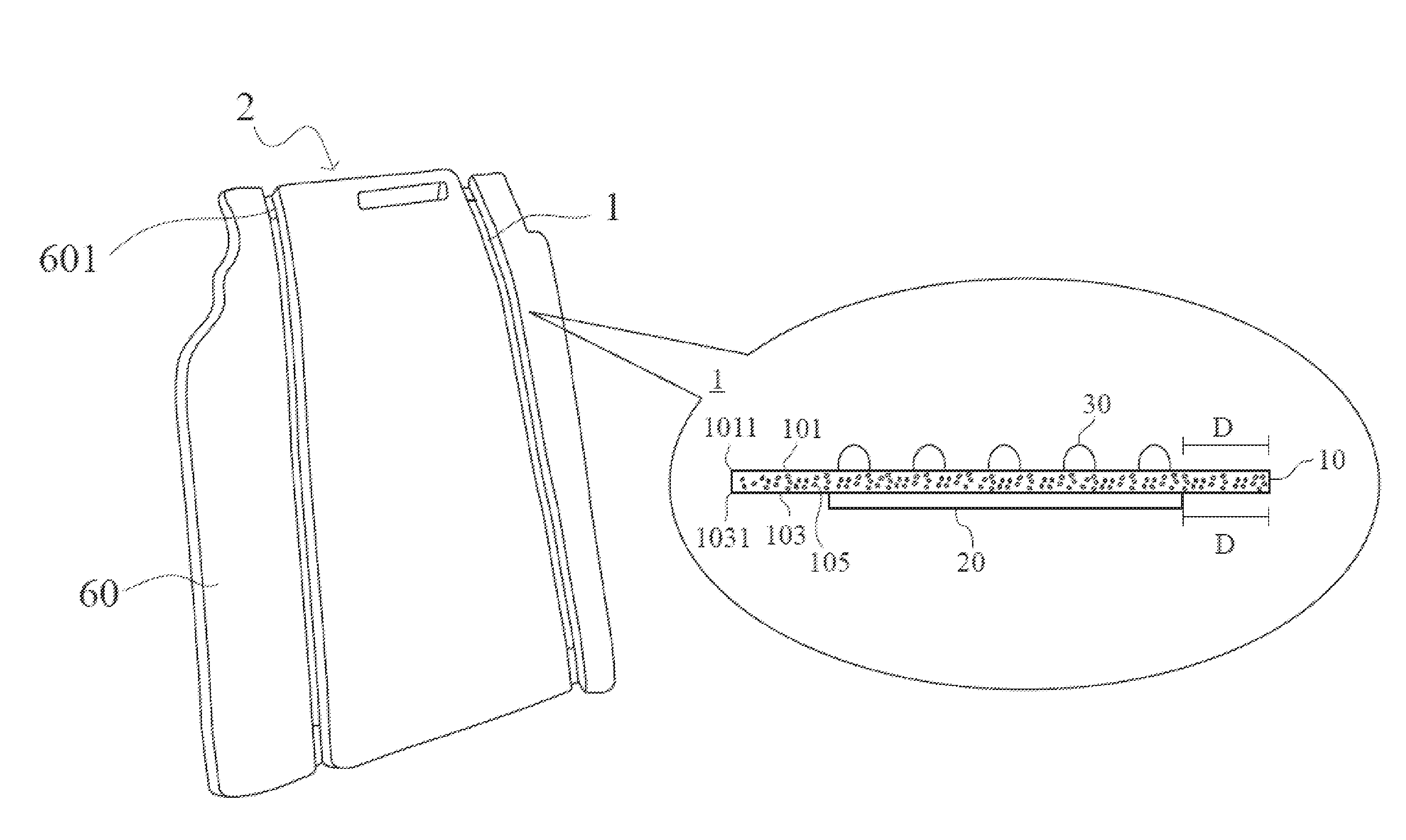
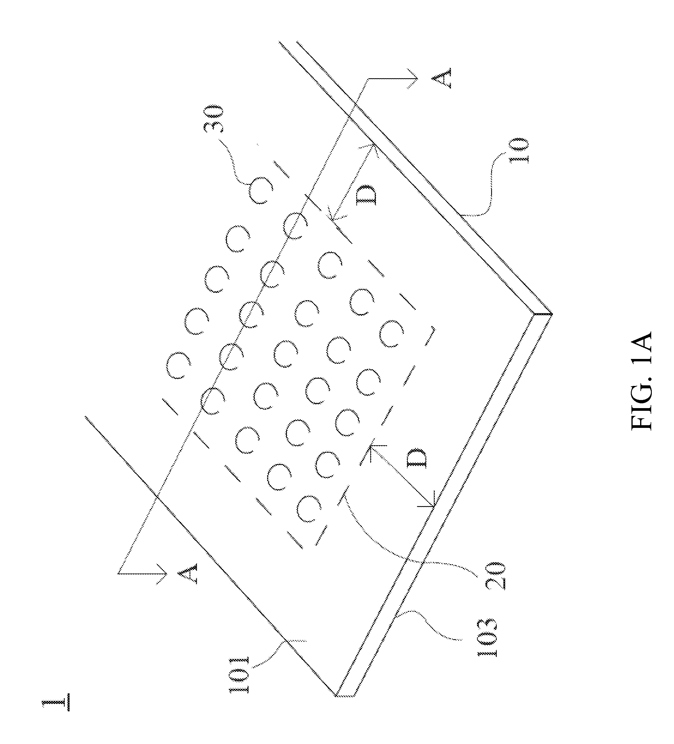
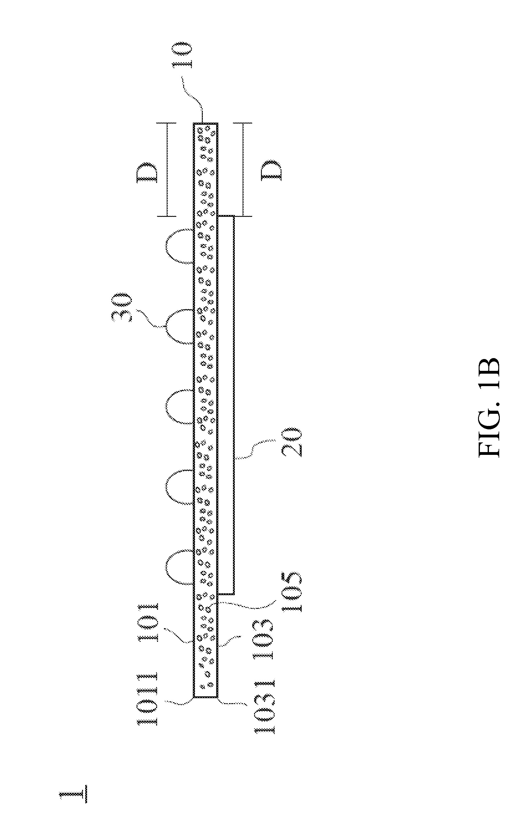
[0020]Please refer to FIG. 1A and FIG. 1B, which are respectively illustrating a view and an A-A line sectional view of FIG. 1A of a hook-and-loop component in one embodiment of the present invention. The hook-and-loop component 1 includes a band body 10, a plurality of hair hoops 30 and a magnetic material 20. The band body includes a first surface 101 and a second surface 103 and the first surface 101 and the second surface 103 are opposite to each other. The material of the band body is nonwoven fabric or fiber fabric and includes a plurality of pores 105. The hair loops 30 are disposed on an area of the first surface 101 of the band body 10 with an interval D existing between a side edge of the disposed area and an edge 1011 of the first surface 101. In addition, in the second surface 103 which is opposite to the first surface, the magnetic material 20 is disposed on an area of the second surface 103 corresponding to the disposed area of the hair loops 30, with the same interval D existing between a side edge of the disposed area of the magnetic material 20 and an edge 1031 of the second surface 103. The magnetic material 20 is preferred to be powder material to include an even magnetic effect and the main material thereof is preferred to be metal powder or metal alloy powder. It is important for the magnetic material to be connected by a magnet.
[0021]Thereafter, please refer to FIG. 2A and FIG. 2B, it is a view illustrating hook-and-loop component to be embedded with a foam material 70 in one embodiment of the present invention. Referring to FIG. 2A and FIG. 2B, because the hook-and-loop component 1 is configured to be embedded with a foam material 70 and exposed the hair loops 30 for connecting, a mold 40 is provided to fix the hook-and-loop component 1 and the foam material 70 can be formed on the hook-and-loop component 1. As shown in FIG. 2A and FIG. 2B, when the hook-and-loop component 1 is to be embedded with the foam material 70, the first surface 101 of the hook-and-loop component 1 is firstly reversed and then disposed on a surface of the mold 40. The mold 40 is provided with a magnet 401 such that the magnetic material 20 on the hook-and-loop component 1 will be attracted by the surface of the mold 40 and the reversed hook-and-loop component 1 is firmly adhered to the surface of the mold 40. In addition, because the hair loops 30 are soft fiber material, the hair loops 30 are pressed to be compact between the reversed hook-and-loop component 1 and the mold 40 when the reversed hook-and-loop component 1 is firmly adhered to the mold 40. As a result, the first surface 101 of the hook-and-loop component 1 is adhered to the surface of the mold 40 because of the magnetic force between the magnet 401 and the magnetic material 20 and there is no gap between the surface of the mold 40 and the first surface 101 of the hook-and-loop component 1.
[0022]Now, please refer to FIG. 2B, it is a view illustrating a foam material 70 is filling the hook-and-loop component 1 within the mold 40 in one embodiment of the present invention. As shown in FIG. 2B, during the foaming process, the foam material 70 fills the pores 105 of the band body 10 in the hook-and-loop component 1 via the area on the second surface 103 with the interval D. Since the reversed hook-and-loop component 1 is firmly adhered to the surface of the mold 40, the hair loops 30 are pressed between the reversed hook-and-loop component 1 and the mold 40 without any gap survive therebetween. That is to say the pores 105 existing between the hair loops 30 and the magnetic material 20 are barred at top and bottom to prevent filling of the foam material 70.
[0023]On the other hand, since the area with the interval D is not provided with the magnetic material 20 on the top and is not provided with the hair loop 30 on the bottom, the first surface 101 of the area with the interval D is not firmly adhered to the surface of the mold 40 and there will be a gap 50 existing between the first surface 101 and the surface of the mold. During the foaming process, the foam material 70 will enter the gap 50 to fill.
[0024]Therefore, the foam material 70 can only fills the pores 105 of the band body 10 in the hook-and-loop component 1 via the area on the second surface 103 with the interval D and via the area on the first surface 101 with the interval D through the gap 50.
[0025]It is to be noted that the foam material 70 will be gradually hardened when filling the pores 105 of the band body 10 in the hook-and-loop component 1, and therefore a proper chosen interval D enables the foam material 70 to fill only the pores 105 within the band body 10 of the area with the interval D and become hardened before reach the pores 105 of the band body 10 of the disposed area of the hair loops 30 and the magnetic material 20.
[0026]As a result, the foam material 70 is only embedded with the portion of the hook-and-loop component having the interval D and covers the edge 1011 of the first surface 101, and the hair loops 30 are not polluted by the foam material 70. Accordingly, not only the hook-and-loop component 1 is firmly embedded with the foam material 70, but also the hair loops 30 are protected from polluting by the foam material 70 during the foaming process. In the present invention, the number, shape or position of the magnet 401 in the mold 40 is not limited herein, as long as the magnet 401 can connect the hook-and-loop component 1.
[0027]Please refer to FIG. 3, it is a view illustrating a chair cushion with the hook-and-loop component in one embodiment of the present invention. As shown in FIG. 3, the chair cushion includes a foam material chair body 60 and at least one hook-and-loop component 1. The foam material chair body 60 and the hook-and-loop component 1 are formed integrally. The hook-and-loop component 1 is the same as the hook-and-loop component 1 is the previous embodiment and includes a band body 10, a magnetic material 20 and a hair loop 30. The hair loops 30 are disposed on the first surface 101 of the band body 10 with an interval D existing between the disposed area and an edge 1011 of the first surface 101. In addition, in the second surface 103 which is opposite to the first surface, the magnetic material 20 is disposed on the corresponding position of the hair loops 30 with the same interval D existing between the disposed area and an edge 1031 of the second surface 103. The characteristic of the components and the connective relationship are the same as the previous embodiment, the detail description is omitted herein. For example, the foam material chair body 60 is embedded within the pores 105 in the edge 1011 of the hook-and-loop component 1 and the foam material chair body 60 covers the edge 1011 of the first surface 101 of the hook-and-loop component 1.
[0028]In addition, in the preferred embodiment, the foam material chair body further includes at least one concave 601 and the hook-and-loop component 1 can be disposed therein to enhance the match of the chair cushion 2 with other components with the corresponding hook-and-loop component (such as chair cushion cover or the hook of the chair back main body).
[0029]The hook-and-loop component provided in the present invention is to substitute the chair cushion with hook to save the process time for extra manufacturing works so as to reduce the manufacturing cost.
[0030]Although specific embodiments have been illustrated and described, it will be appreciated by those skilled in the art that various modifications may be made without departing from the scope of the present invention, which is intended to be limited solely by the appended claims.

PUM

no PUM

Description & Claims & Application Information

We can also present the details of the Description, Claims and Application information to help users get a comprehensive understanding of the technical details of the patent, such as background art, summary of invention, brief description of drawings, description of embodiments, and other original content. On the other hand, users can also determine the specific scope of protection of the technology through the list of claims; as well as understand the changes in the life cycle of the technology with the presentation of the patent timeline. Login to view more.

Similar technology patents

Display Device

ActiveUS20100277448A1less breakagecost reduction
Owner:SEMICON ENERGY LAB CO LTD

One-time programmable memories using polysilicon diodes as program selectors

ActiveUS20120044738A1small cell sizecost reduction
Owner:ATTOPSEMI TECH CO LTD

Spray non-contact cutting type antenna and its fabrication method

InactiveUS20100033400A1save manufacturing timelower defect rate
Owner:AUDEN TECHNO

Fetching application and driver for extension device from network

ActiveUS7062260B2reduce memory requirementcost reduction
Owner:IRONWORKS PATENTS LLC

Basic polymer electrolyte fuel cell

InactiveUS6986962B2cost reductionhigh output
Owner:HONDA MOTOR CO LTD

Item substitution in the manufacture of products

ActiveUS7343212B1eliminate and reduce inefficiency and other problem associatecost reduction
Owner:CRESCENTONE INC

Classification and recommendation of technical efficacy words

  • cost reduction
  • save manufacturing time

Floorboards, flooring systems and methods for manufacturing and installation thereof

ActiveUS20040139678A1increase wear resistancecost reduction
Owner:VÄLINGE INNOVATION AB

Light emitting sign and display surface therefor

InactiveUS20070240346A1cost reductionwell light uniformity
Owner:INTEMATIX

Gas-phase chemical reactor and method of using same

ActiveUS20190376180A1less wastefulcost reduction
Owner:ASM IP HLDG BV

Spray non-contact cutting type antenna and its fabrication method

InactiveUS20100033400A1save manufacturing timelower defect rate
Owner:AUDEN TECHNO
Why Eureka
Try Eureka