

Filter Structure, Welding Fixture, and Manufacturing Method of the Filter Structure
- Summary
- Abstract
- Description
- Claims
- Application Information
AI Technical Summary
Benefits of technology
Problems solved by technology
Method used
Image

Examples
Embodiment Construction
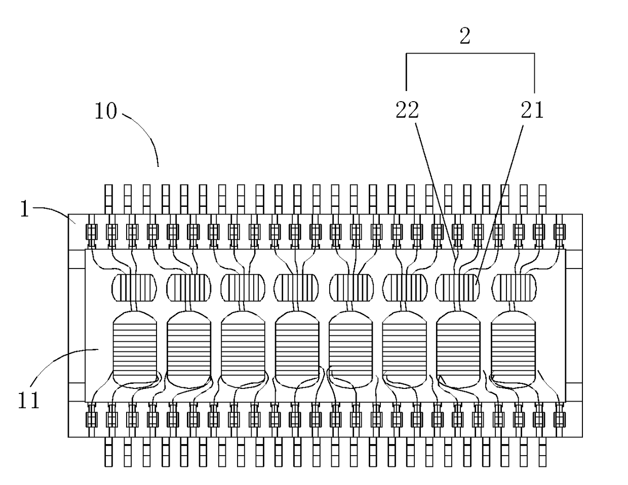
[0035]The invention discloses a filter structure comprising: a box having a cavity; a plurality of coil components installed in the cavity; and a plurality of wiring components. Each wiring component has a positive wiring pin and a negative wiring pin fixed to the box; wherein the conductive wire has conductive wires coupled to both ends of the coil component and welded and fixed to the positive and negative wiring pins respectively by spot welding or melting.
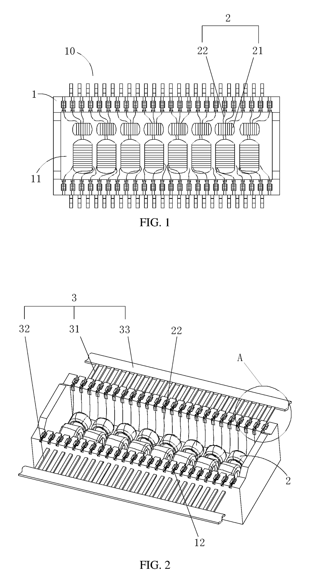
[0036]With reference to FIGS. 1, 2, and 3 for a filter structure 10 in accordance with the present invention, the filter structure 10 comprises a box 1 having a cavity 11, and a coil component 2 and a wiring component 3 installed in the cavity 11. Specifically, there are eight groups of coil components 2, and 24 groups of wiring components 3, and each group of coil components 2 has three conductive wires 22.
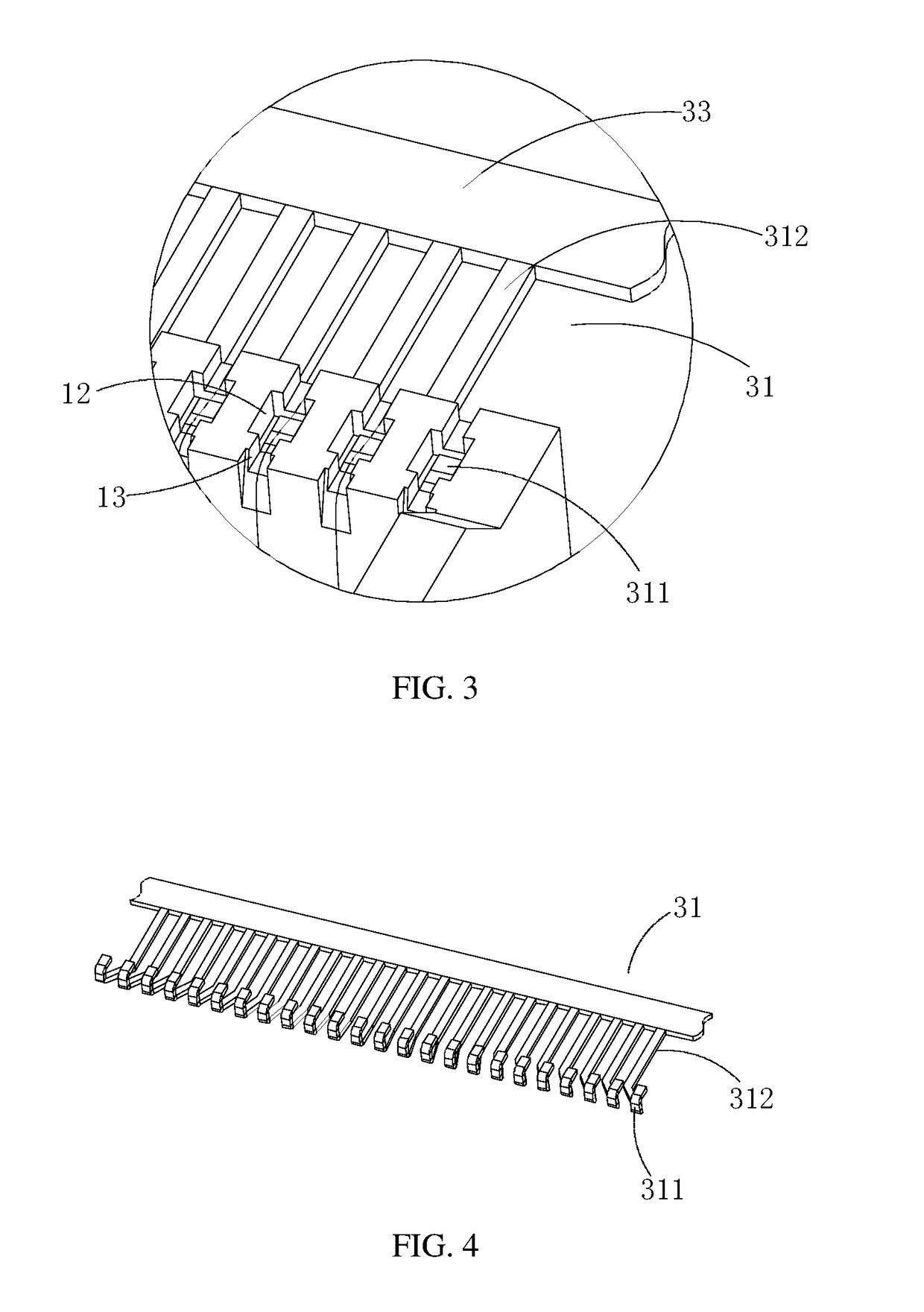
[0037]The wiring component 3 includes a positive wiring pin 31 and a negative wiring pin 32 fixed to the box 1, and conduc...
PUM
| Property | Measurement | Unit |
|---|---|---|
| Electrical conductor | aaaaa | aaaaa |
Abstract
Description
Claims
Application Information