

Outlet box assembly
- Summary
- Abstract
- Description
- Claims
- Application Information
AI Technical Summary
Benefits of technology
Problems solved by technology
Method used
Image

Examples
Embodiment Construction
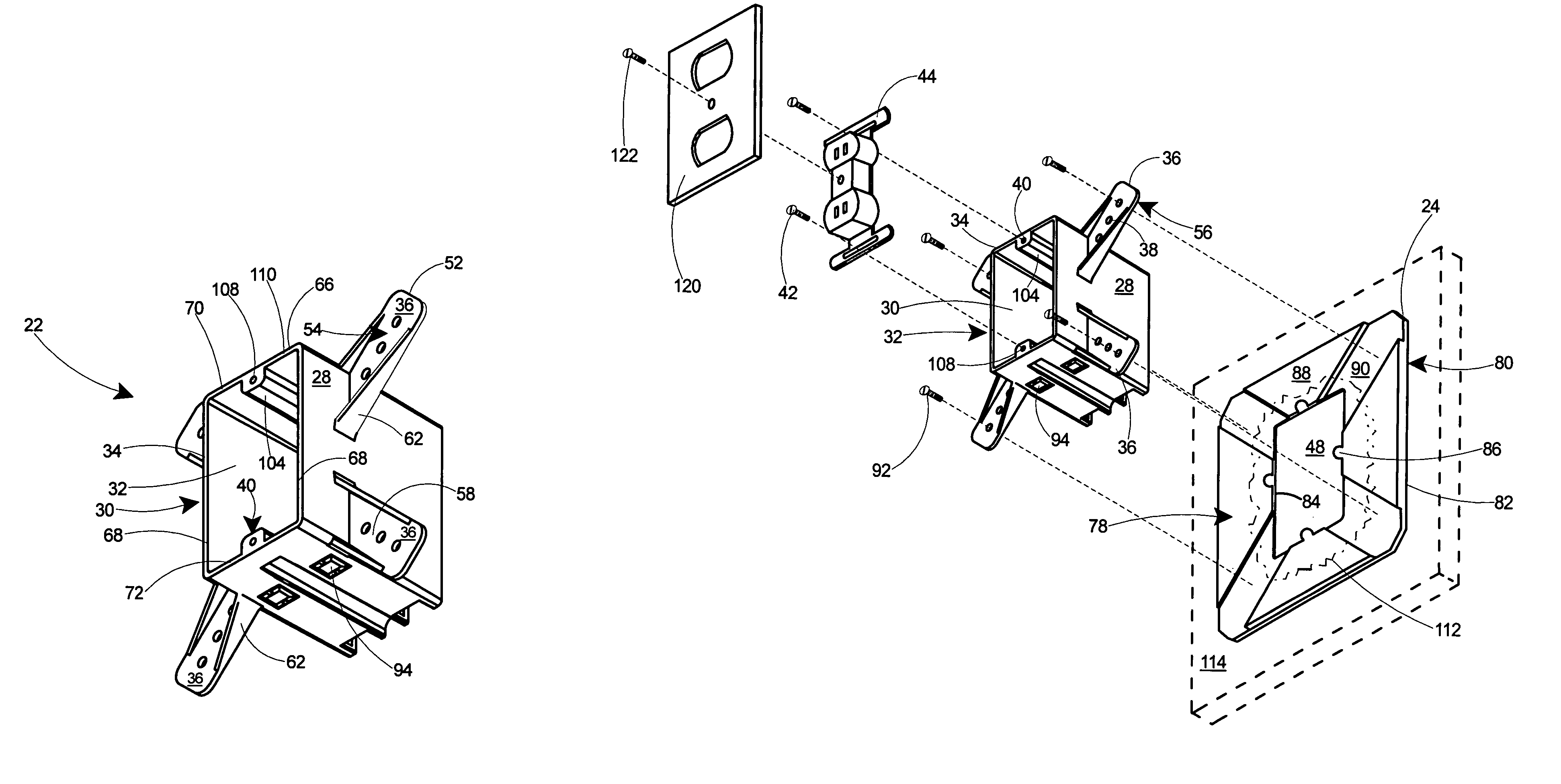
[0027]The present invention is an outlet box assembly for securing an electrical device on a block wall. The outlet box assembly can be easily installed on a block wall. When installed on a wall with an electrical device installed therein, the outlet box assembly provides a visually attractive electrical outlet, switch, or other electrical device. If the block wall is later finished with drywall, stucco, or a similar wall covering, the outlet box assembly includes a planar front edge that extends outwards from the wall, thereby situating the outlet box approximately even with the finished wall surface.
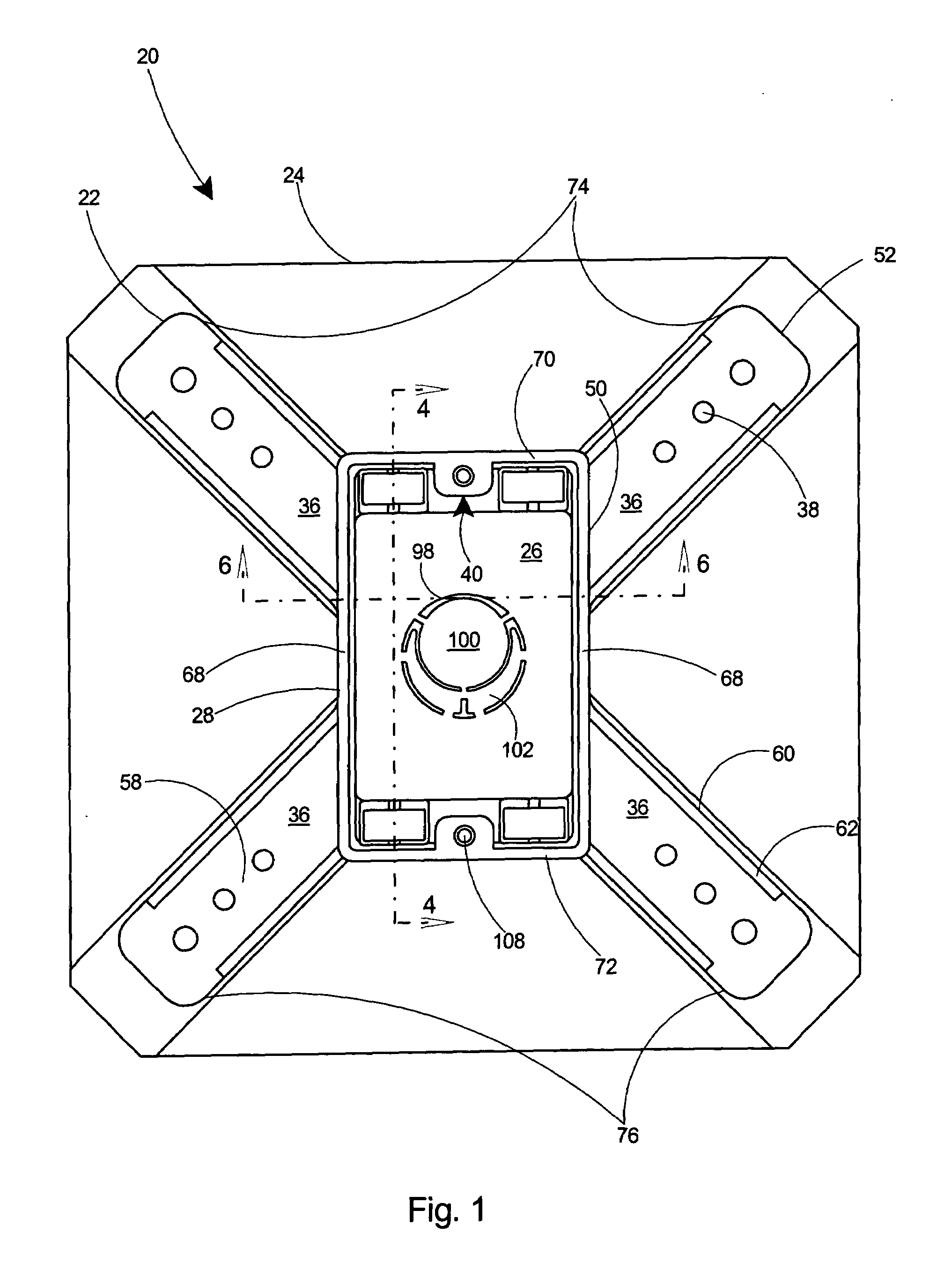
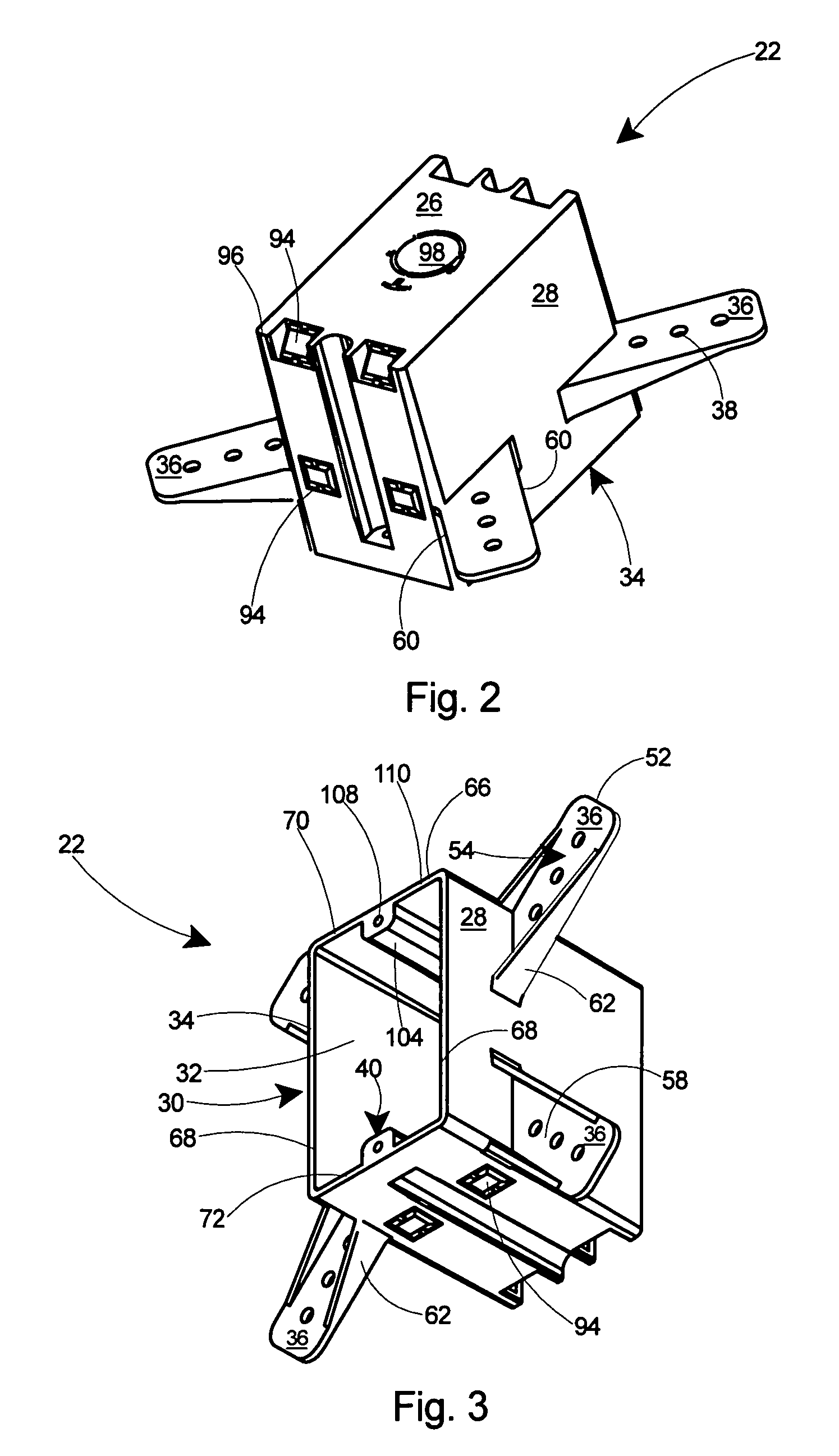
[0028]Referring to FIGS. 1 and 7, an outlet box assembly 20 according to the present invention includes a housing 22 and a base plate 24. The housing 22 includes a planar back wall 26, integral peripheral sidewalls 28, and an open front 30 defining an enclosure 32 therein. The housing 22 further includes a planar front edge 34 at the open front 30 with the planar front edge 34 in a par...
PUM
 Abstract
Description
Claims
Application Information