Tool and method for controlled cutting

Inactive Publication Date: 2012-09-20
HOLTGREIVE MR JOSEPH JOHN
View PDF31 Cites 14 Cited by
  • Summary
  • Abstract
  • Description
  • Claims
  • Application Information

AI Technical Summary

Benefits of technology

[0019]An important object of this invention is to provide an improved apparatus and means for achieving pro

Problems solved by technology

The prior art devices designed to execute a measured and precise straight or angled cut in the aforementioned materials are either inadequate or expensive and cumbersome.
There are a number of devices that attempt to address one or more of these elements as related to the execution of a strait or angled cut, none of which successfully address all of these elements simultaneously at a cost that is universally embraced by the non-professional.
The results of this work around often lack the professional results users seek.
The process disclosed by Levin, however, d

Method used


Image

  • Tool and method for controlled cutting
  • Tool and method for controlled cutting
  • Tool and method for controlled cutting

Examples


third embodiment

[0058]Referring to FIGS. 14, 15, and 16, a third exemplary embodiment of the template cutting guide 60 is shown with the base elements of embodiment one of the template cutting guide 20 of the present invention. Within the template cutting guide 60 of this embodiment are a series of interspersed windows 61 with side walls 62&63 and end walls 64&65 forming a rectangular window 61. Windows 61 may be used to view the outer peripheral edges of the workpiece 4 when registering the edges for the desired offset. This third embodiment also has gripping ridges 66 protruding from the bottom of the template cutting guide 60 for enhanced gripping of the workpiece 4 when cutting. The gripping ridges may have a raised peak 67 designed to direct the forces in a point loading mechanical advantage for securing the template cutting guide 60 to the workpiece 4 during cutting. Using this embodiment the user would use the windows 61 to view the workpiece 4 alignment to the series of longitudinal and lat...

embodiment 2

[0059]Referring to FIGS. 18, 19, 20, and 21, none of the embodiments are intended to be defined by the shown push pin design, as one skilled in the art can understand any number of push pin designs may be employed for the purpose of securing the template cutting guide 20, 40, or 60 to the workpiece 4. Thus, it is proposed for this disclosure to use a commonly available push pin design to facilitate this function. FIG. 18 shows a perspective view of one such push pin, having a body 79 and a needle portion 75. The push pin needle 75 has a sharp terminating pin tip 78 to facilitate penetrating the workpiece 4 when securing the template cutting guide 20, 40 or 60 to the workpiece 4. A base section at the push pin bottom 77 of the push pin body 79 acts in this design as a stopping surface when the push pin is inserted and pushed in to the workpiece 4 and in embodiment 2 through the push pin guide pocket 72. As seen in FIG. 21, the push pin guide pocket 72 may be designed to receive the p...


PUM

PropertyMeasurementUnit
Thicknessaaaaaaaaaa
Angleaaaaaaaaaa
Transparencyaaaaaaaaaa

Abstract

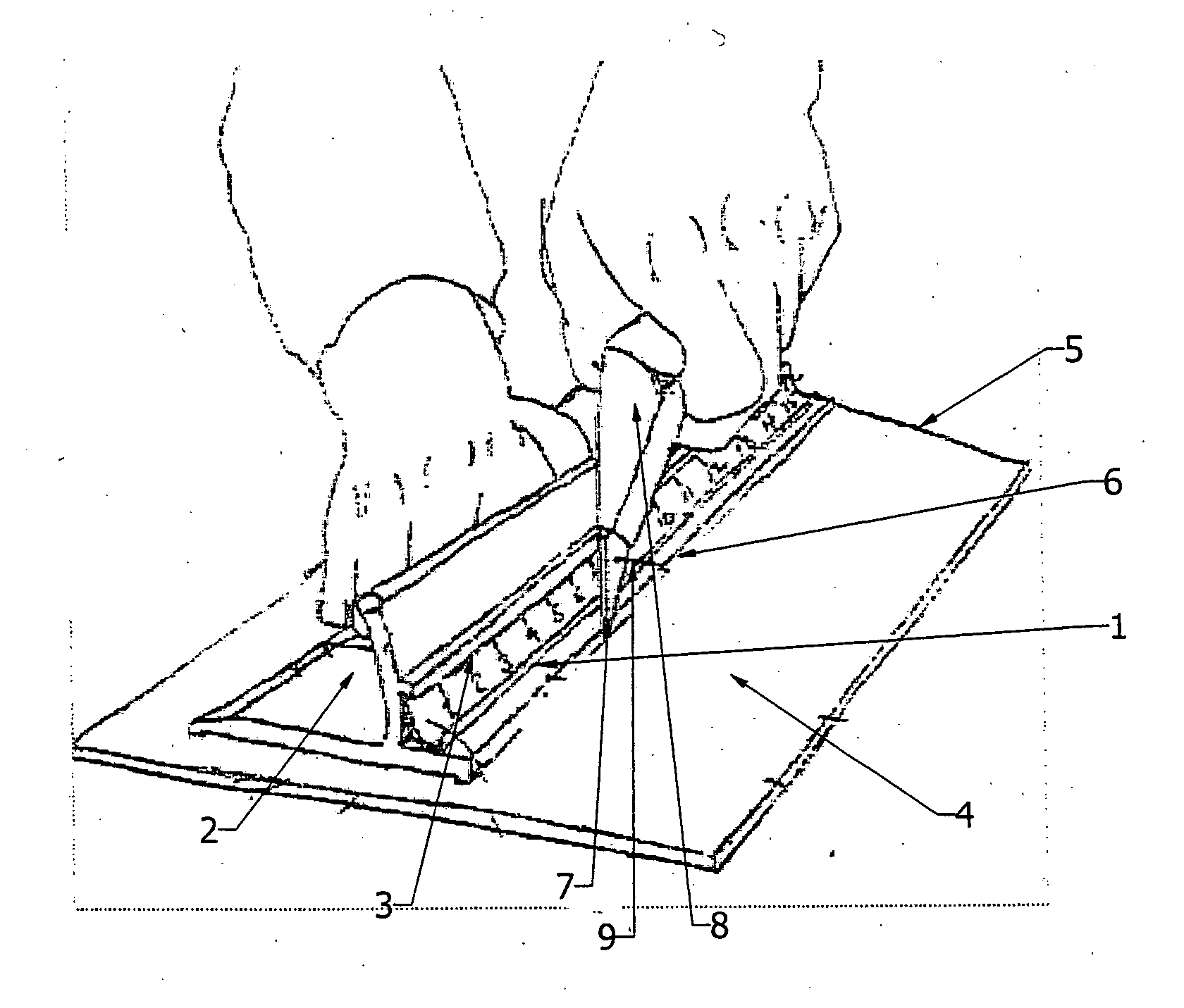
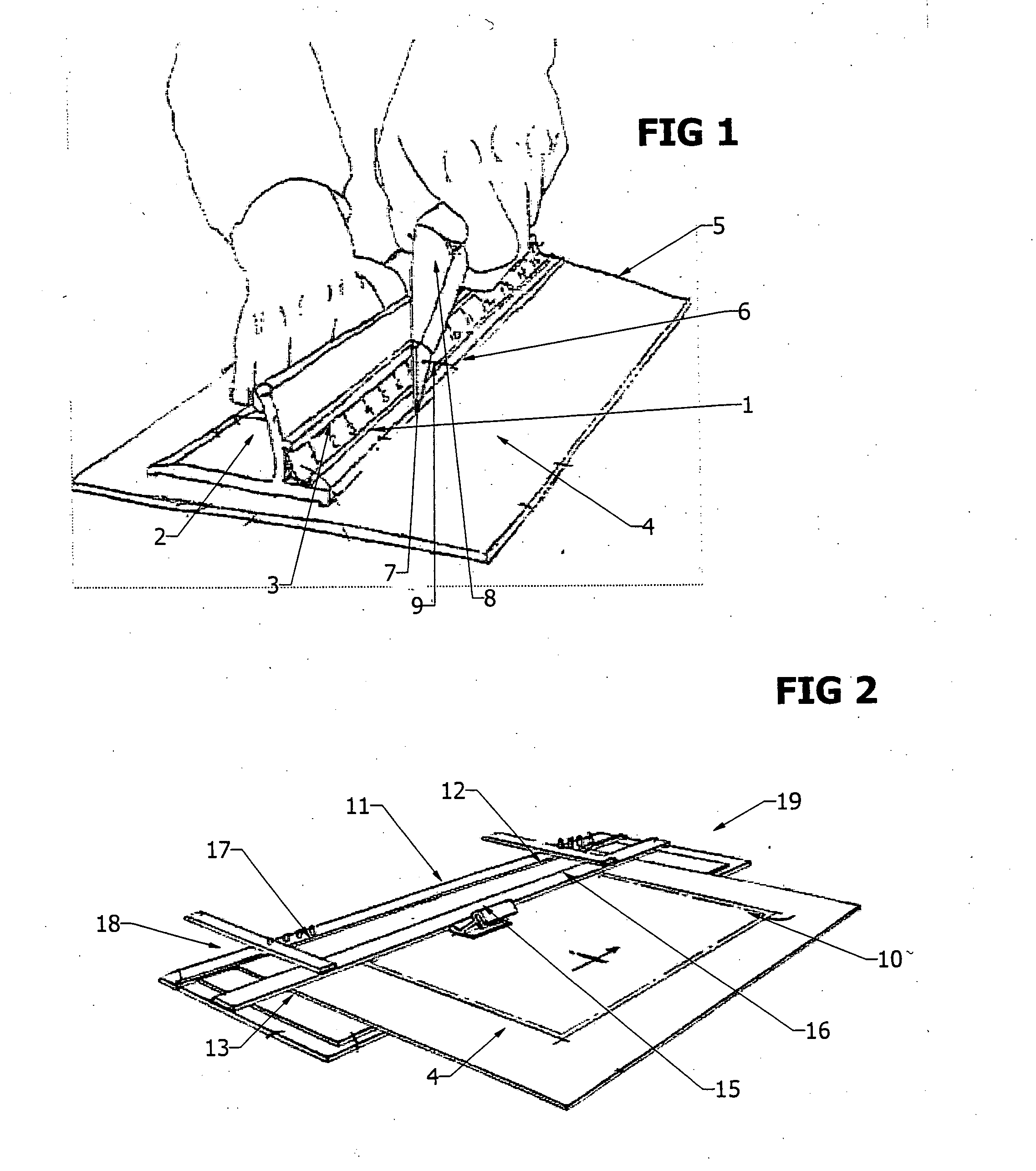
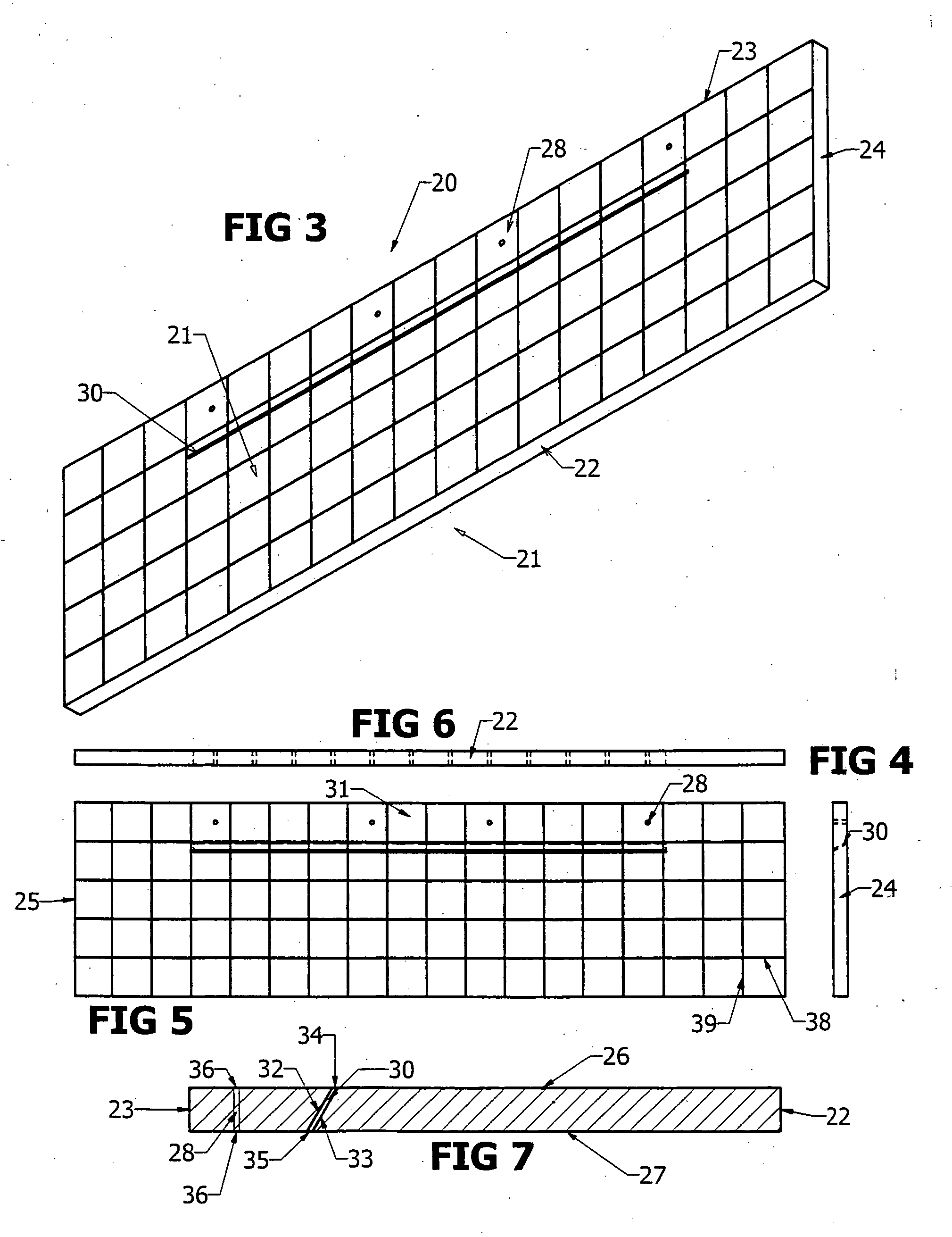
A Tool and method for making controlled cuts using a templete cutting guide to facilitate the registration and cutting of a workpiece including, an elongated body portion having a top face and a bottom face separated by a thickness, a cutting guide slot sized to receive a cutting blade and extending through the thickness of the elongated body which may include guide lines with equidistant spacing, additionally the cutting guide may utilize push pins or fasteners to secure the cutting guide to the workpiece. The purpose of this cutting guide is to allow the user the means of achieving professional results at a lower cost and with less time and effort when executing precise cuts in material such as mat board using a standard utility knife and the cutting guide of this invention.

Description

BACKGROUND OF THE INVENTION[0001]The present application claims priority to U.S. Provisional Application No. 61 / 404,038, filed Sep. 27, 2010, which is incorporated by reference.[0002]1. Field of the Invention[0003]The present invention relates to a template for a cutting tool and, more particularly, to a guide for easily measuring and positioning the template for creating cuts onto a substrate.[0004]2. Description of the Related Art[0005]Various materials, such as, mat board, construction board, foam board, paper and corrugated paper are often cut to size or have cut outs within their borders. Many times determining the location of the cuts is a multi-step process requiring measuring, marking and finally positioning a tool to guide the blade or placing the substrate into a fixture to facilitate cutting.[0006]The practice of creating a mat window within a frame by measuring and cutting out a center section of material such as mat board, foam board, paper and corrugated paper to creat...

Claims


Application Information

Patent Timeline
IPC IPC(8): B26D5/08
CPCB26B29/06B26F1/3853Y10T83/7507Y10T83/8821
Inventor HOLTGREIVE, JOSEPH JOHN
Owner HOLTGREIVE MR JOSEPH JOHN
Why Eureka
Try Eureka