Maximum propulsion attachment for grass mower

a mower and maximum propulsion technology, applied in the field of self-propelled, walk-behind, grass mowers, can solve problems such as inability to driv

Inactive Publication Date: 2006-05-11
KOHLER JOSEPH EDWARD
View PDF12 Cites 3 Cited by
  • Summary
  • Abstract
  • Description
  • Claims
  • Application Information

AI Technical Summary

Problems solved by technology

It is shown that this is not possible with prior art, due to the limit of coefficient of friction between uncut grass and prior art tires.

Method used


Image

  • Maximum propulsion attachment for grass mower
  • Maximum propulsion attachment for grass mower
  • Maximum propulsion attachment for grass mower

Examples


Embodiment Construction
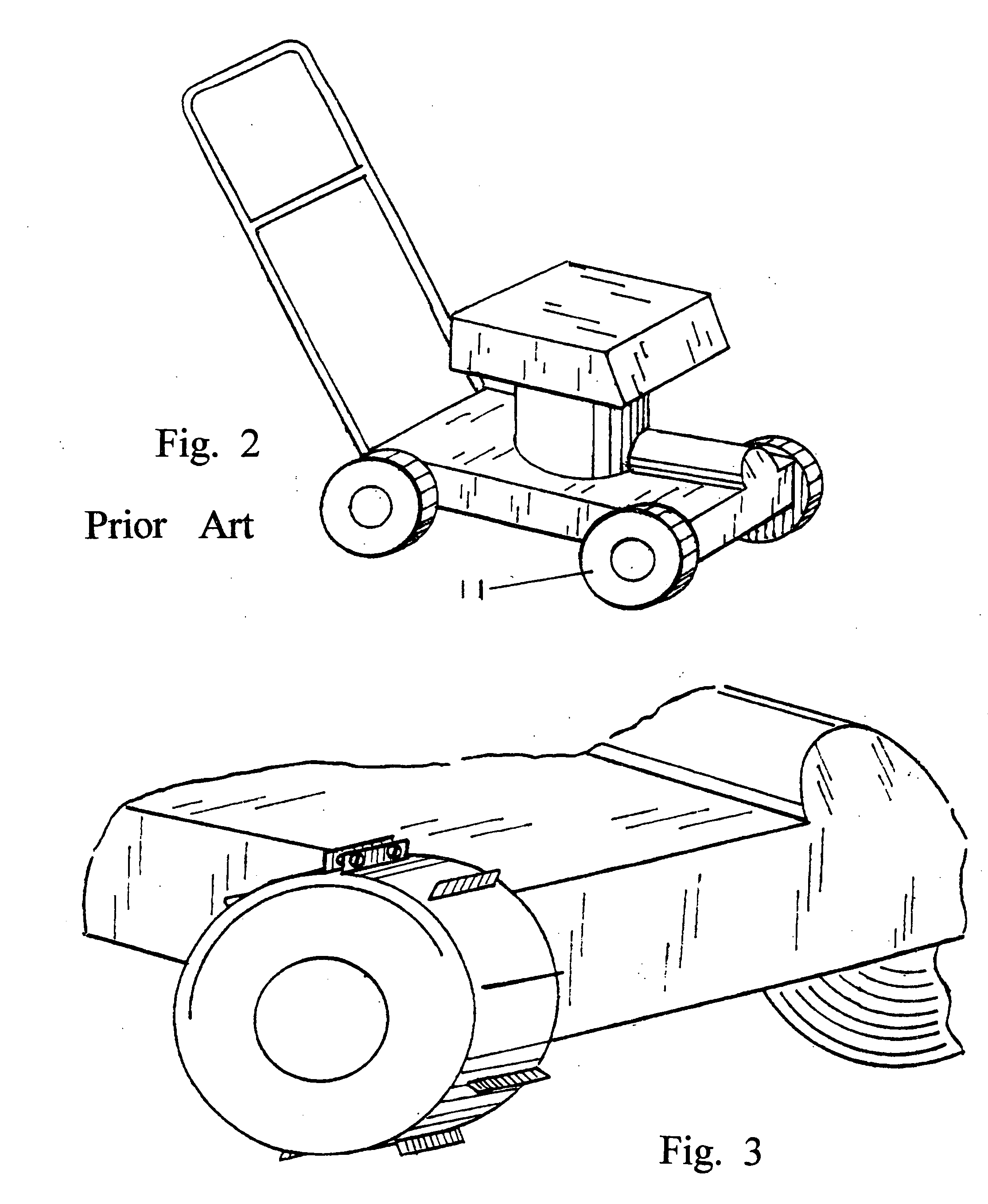
—FIG. 1 TO FIG. 3

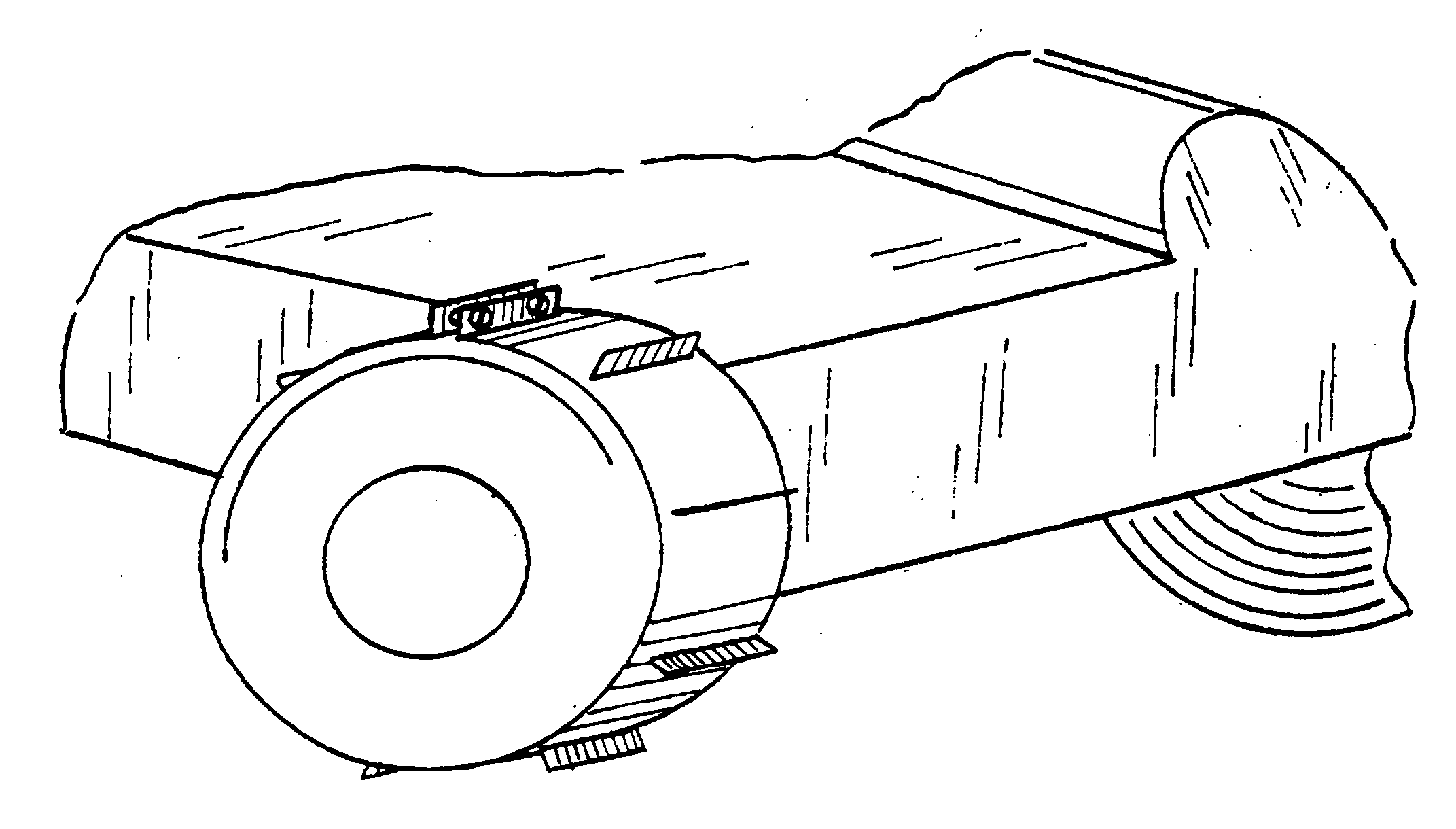
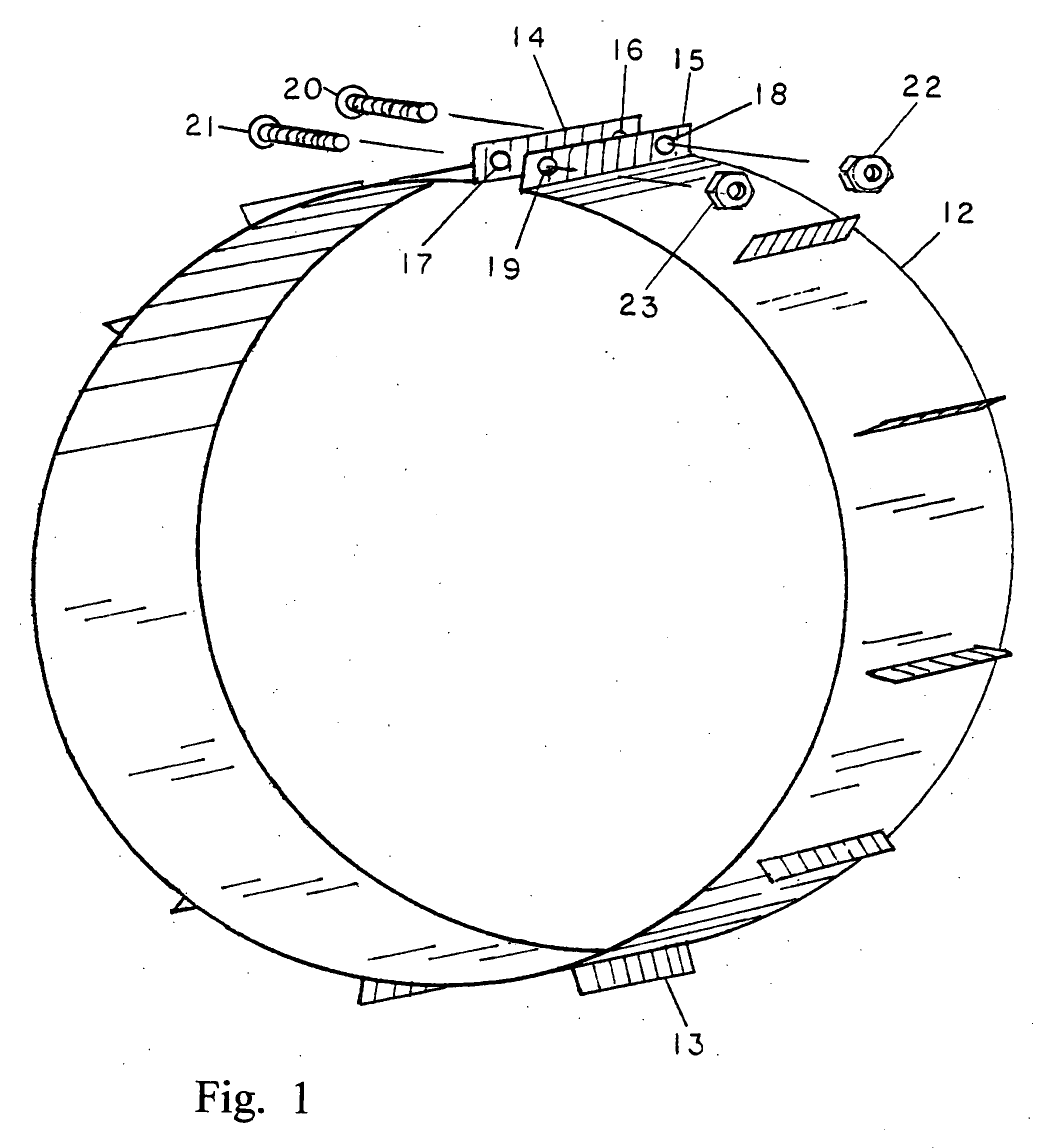
[0050]FIG. 1 shows a basic perspective of the invention. The thin band 12 is 2 inches wide, 25 inches long and 0.032-0.060 inches thick metal. Hard brass is a suitable material, as soldering of parts to it will follow. I used a door kick plate to fashion all sheet parts.

[0051] The thin paddle 13 is ¼ inch wide, 1½ long and also fabricated from the same material as thin band 12. There are 15 paddles soldered to the thin band 12 at a spacing every 1.5 inches. If one uses a lesser spacing with more paddles, the coefficient of friction to grass diminishes. If fewer paddles are used at a greater spacing, you will get something you won't like, grass demolition.

[0052] But, before any soldering is commenced, it is easiest to make 90 degree bends of ¼ inch height on each end of the thin metal band, 12. These are bend 14 and bend 15. Fabricate a ⅛ diameter hole at each of the four corners of bend 14 and bend 15. This is hole 16, hole 17, hole 18, and hole 19. A 6-32 thread ...


PUM


Abstract

This device attaches to drive tires of walk-behind grass mowers to provide several new advantages. Foremost, the drive tire grip to uncut grass is more than increased, it is maximized, resulting in a true self-propelled, walk-behind mower. No pushing is required, even when ascending steep inclines. Thus, minimum time and effort is expended to mow lawns. By attaching this device to old and worn drive tires, they are easily, quickly, and economically, given better than new performance. Finally, by attaching this device to grass mower drive tires, this new assembly lasts many times longer than the original.

Description

BACKGROUND OF THE INVENTION [0001] 1. Field of Invention [0002] This invention relates to self-propelled, walk-behind, grass mowers [0003] 2. Prior Art [0004] Walk-behind grass mowers have evolved to two basic types. The economy model has no propulsion system. It depends on the operator for the driving force. This can become a grueling experience. [0005] The luxury model is self-propelled. A motor drives the cutting mechanism and rotates two tires. This type mower has drive tires either ahead of the cutting mechanism or behind the cutting mechanism. With this class of mower, the operator is led to expect complete relief of exertion. As we shall see, the operator gets something less. [0006] Now, self-propelled, walk-behind mowers utilize 8 inch diameter tires of a rubber like material with some type of tread pattern. To uncloak the not so obvious defective prior art propulsion, two tools are needed: A 0-50 pound fish spring scale and the concept of coefficient of friction. [0007] Let...

Claims


Application Information

Patent Timeline
Patent Type & Authority Applications(United States)
IPC IPC(8): A01D45/02
CPCA01D34/82
Inventor KOHLER, JOSEPH EDWARD
Owner KOHLER JOSEPH EDWARD
Why Eureka
Try Eureka