Hinge

Inactive Publication Date: 2007-09-27
LEE HOONG THYE ELDON
View PDF8 Cites 5 Cited by
  • Summary
  • Abstract
  • Description
  • Claims
  • Application Information

AI Technical Summary

Benefits of technology

[0005] It is an object of this invention to provide a hinge capable of being i

Problems solved by technology

If this is fabricated in a factory, as they usually are, the hinges face the problems of alignment, trimming, cutting doors, relative hinge positions changed, etc, due to differences in floor to ceiling heights depending on location and premises.
The alternative is to customize the

Method used


Image

  • Hinge
  • Hinge
  • Hinge

Examples


Example

[0017] The objective of the invention is to allow the hinge to be secured to a door and frame directly without the need to chisel or shape the door or frame to create a recess to accommodate the flanges of the hinge.

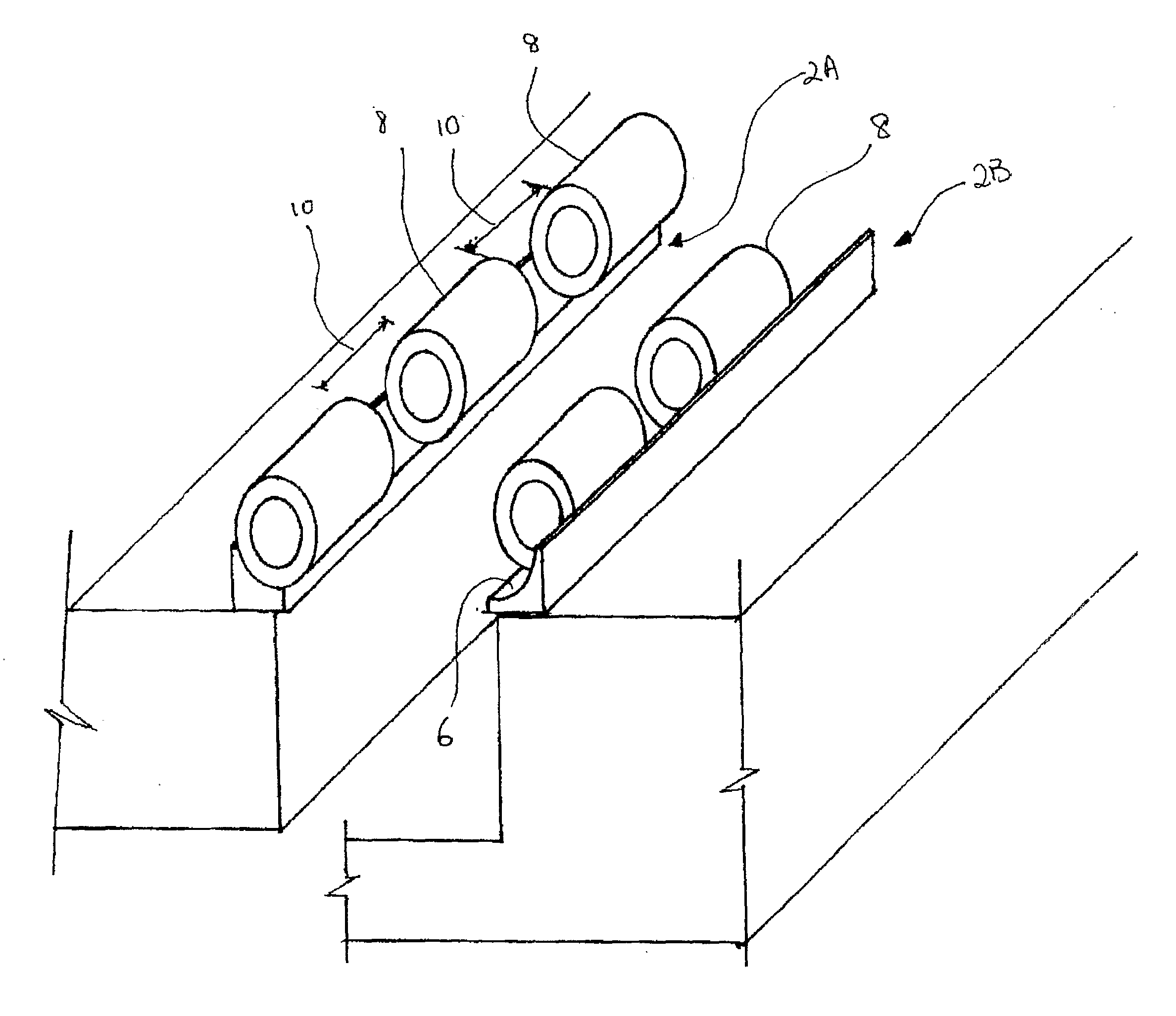
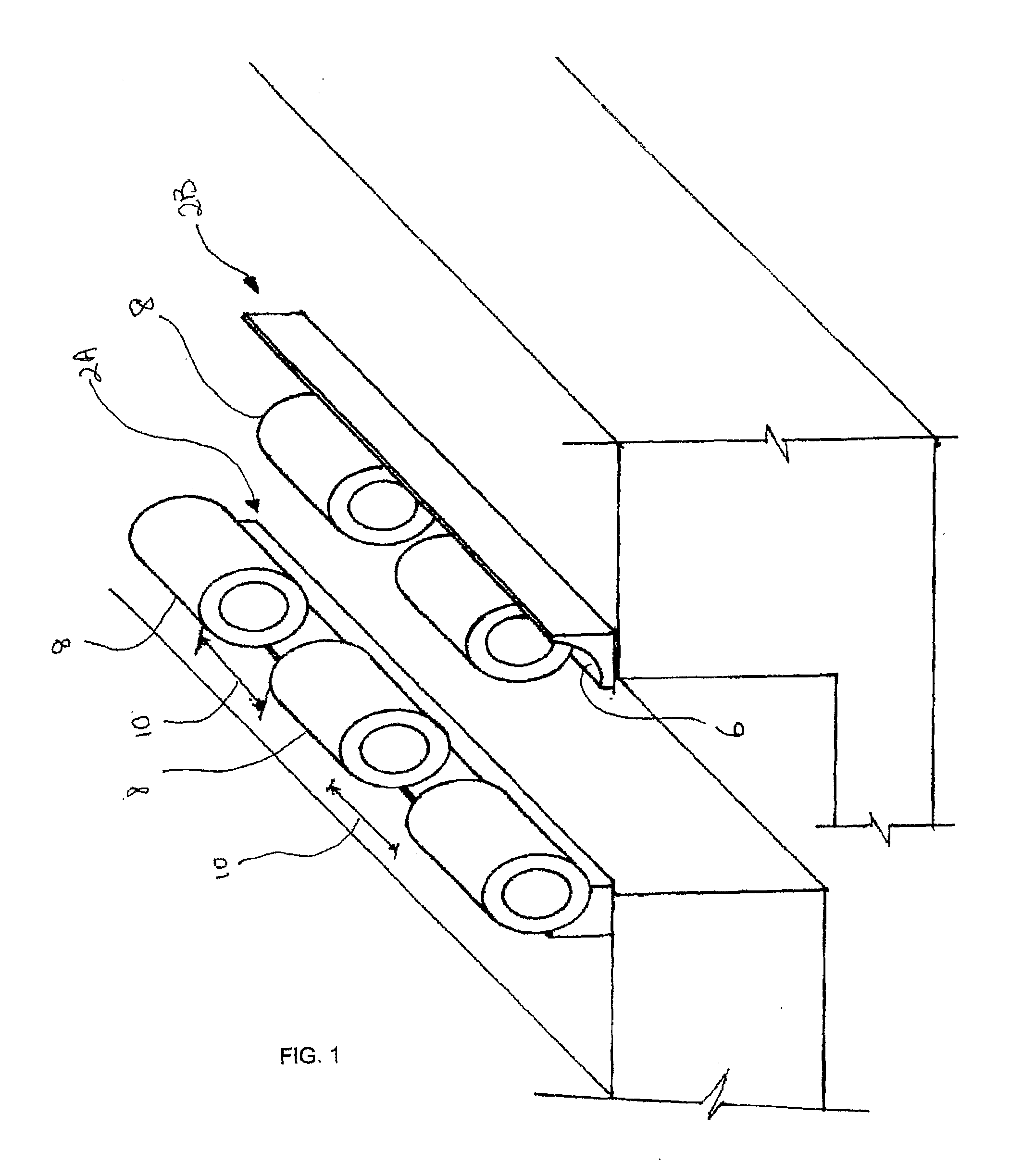
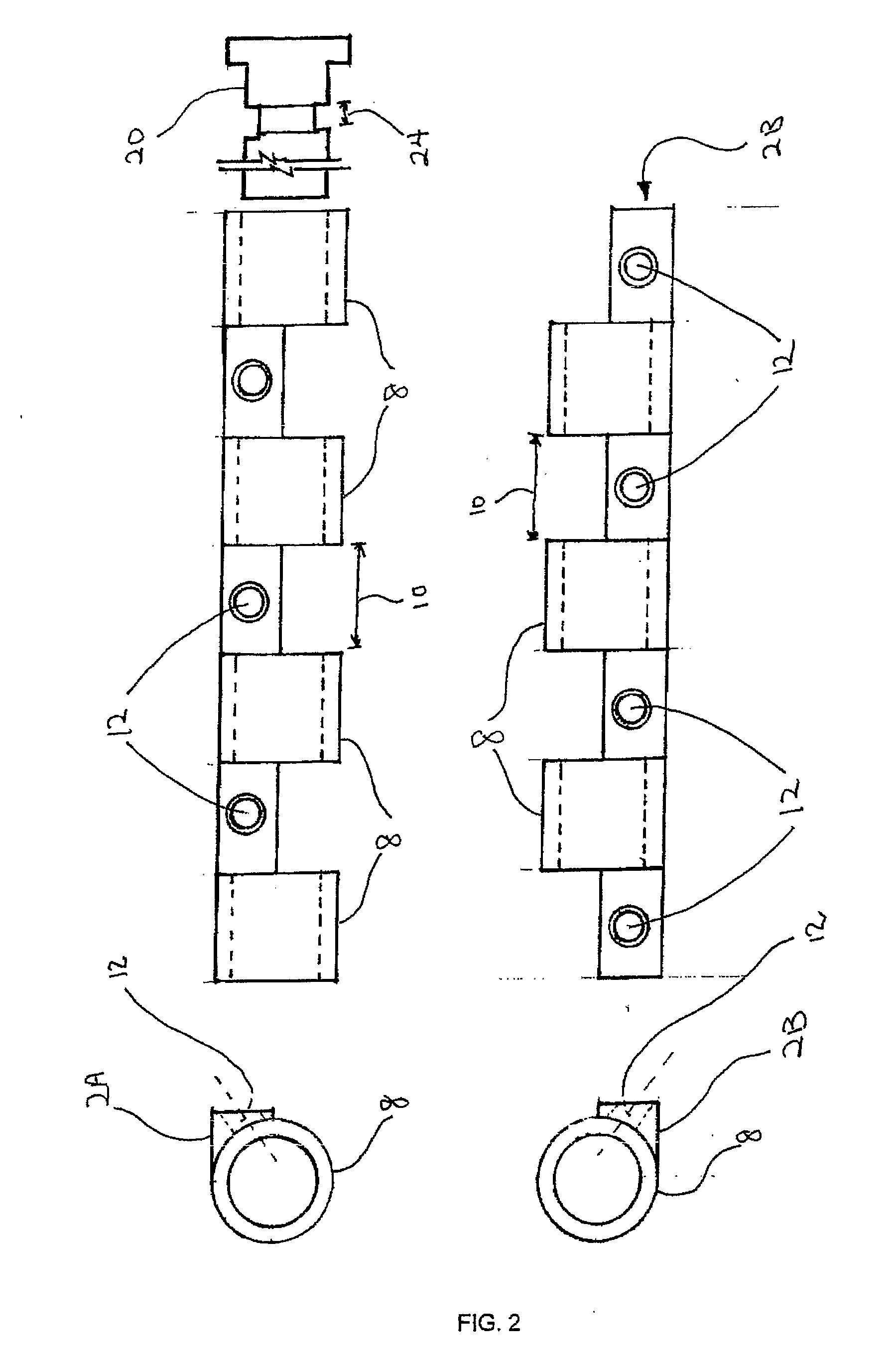
[0018] In one preferred embodiment, the hinge comprises a base 2A preferably constructed with a concave surface 6 to receive a quadrant of a hollow cylinder 8 so that the latter sits snugly in the concave surface of the base. A plurality of hollow cylinders are fixed and spaced along the base. For the ease of manufacture, the space 10 should preferably be of equal dimension.

[0019] A fixer hole 12 is machined into the concave surface of the base where the space 10 is located. The hinge would be secured to a door or frame through these fixer holes.

[0020] The hinge comprises another counterpart base 2B of a similar configuration. The hinge is completed by both bases meeting by fitting the cylinders 8 on one base 2A into the space 10 of the other base 2B.

[0021] To instal...


PUM


Abstract

A hinge having two bases (2A/2B) on which a plurality of hollow cylinders (8) are arranged axially and spaced along each of the bases. Fixer holes (12) are provided in the bases at the spaces (10) between the cylinders to enable the hinge to be mounted directly without the need to work the mounting surface. The bases may be constructed to conceal the mounting screws (18).

Description

1. BACKGROUND OF INVENTION [0001] The present invention relates to hinges for use generally on doors. [0002] Traditionally butt hinges are constructed using a central pin from which two flanges extend. These hinges need to be chiseled and mortised into timber doors or recessed into metal doors with reinforcement plates. If this is fabricated in a factory, as they usually are, the hinges face the problems of alignment, trimming, cutting doors, relative hinge positions changed, etc, due to differences in floor to ceiling heights depending on location and premises. [0003] The alternative is to customize the hinges on site but due to current hinge designs, much carpentry and metalworking is required to install the hinges into the door. This is one of the main reasons for the excessive amount of time and effort currently required to install door hinges and to mount the door to its frame. [0004] This does not obviate the parts of the hinge from being observable on the edge of the door lea...

Claims


Application Information

Patent Timeline
IPC IPC(8): E05D7/00
CPCE05D5/02E05D7/009E05D11/00Y10T16/558Y10T16/52Y10T16/554E05D11/0018E05D3/02E05D3/04E05D7/00
Inventor ELDON, LEE HOONG THYE
Owner LEE HOONG THYE ELDON
Why Eureka
Try Eureka