Display device

Inactive Publication Date: 2012-09-20
SHARP KK
View PDF0 Cites 13 Cited by
  • Summary
  • Abstract
  • Description
  • Claims
  • Application Information

AI Technical Summary

Benefits of technology

[0008]According to such a configuration, the difference image processing can be simplified, and therefore, it becomes possible to provide a disp

Problems solved by technology

That is, the conventional configuration has a problem in that, due to a need f

Method used


Image

  • Display device
  • Display device
  • Display device

Examples


Example

Embodiment 1

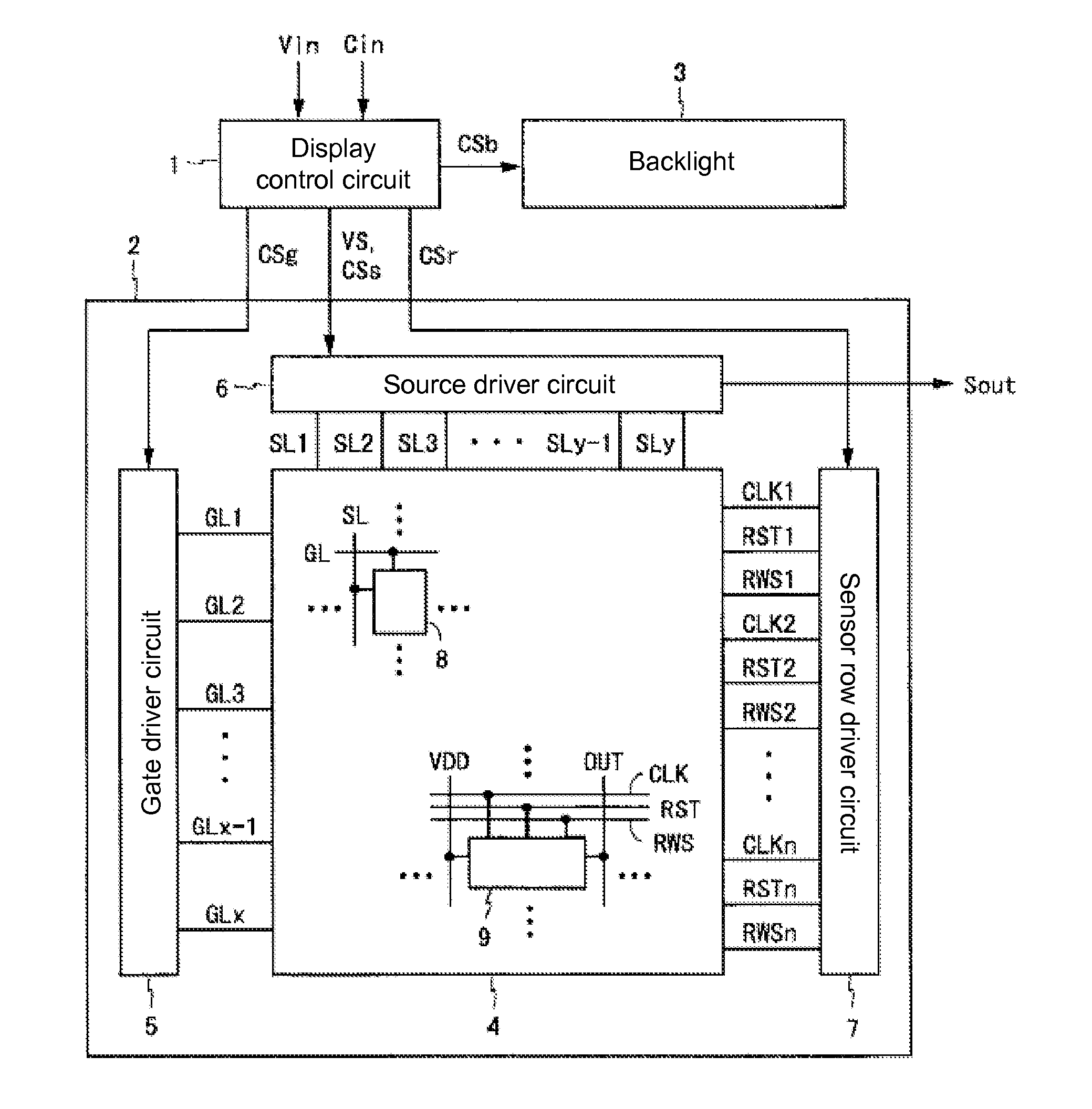
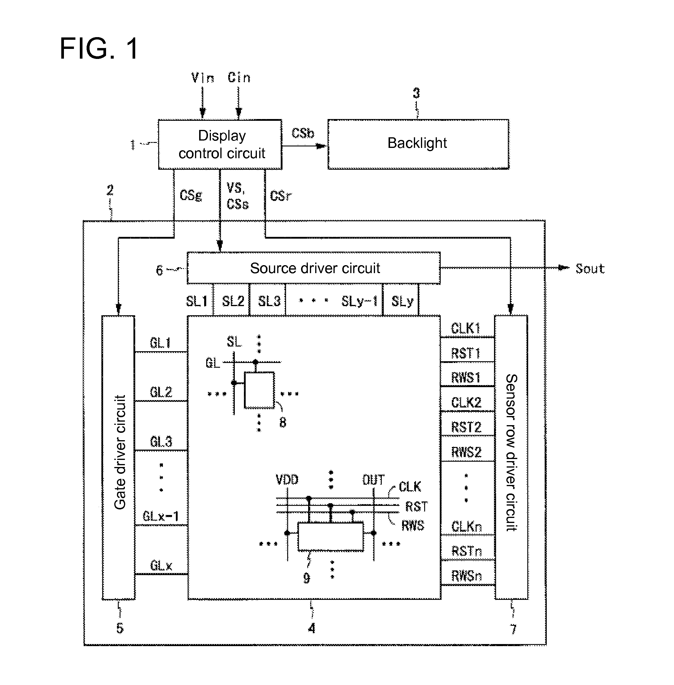
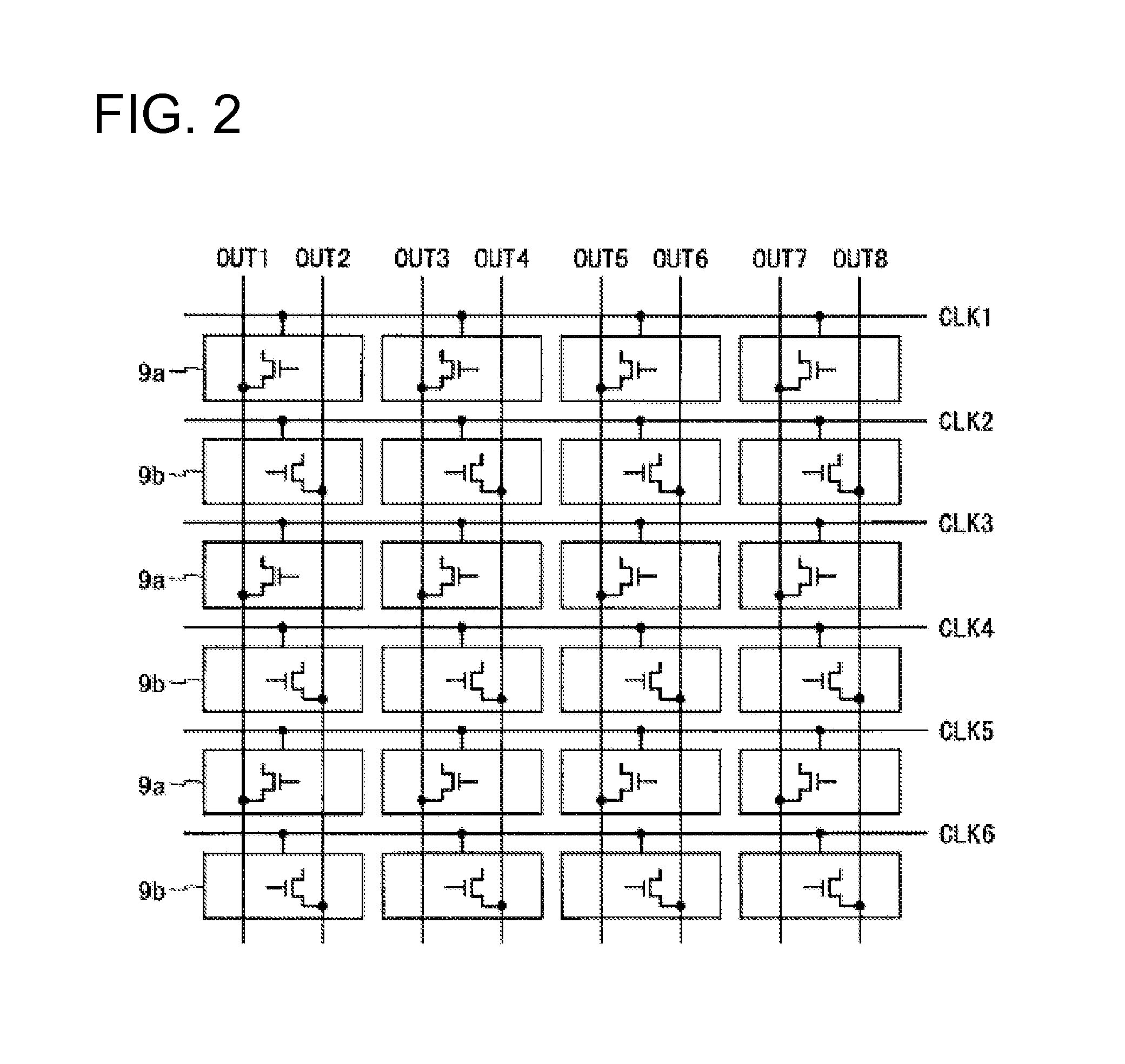
[0037]FIG. 1 is a block diagram showing a configuration of a display device according to an embodiment of the present invention. The display device shown in FIG. 1 includes a display control circuit 1, a display panel 2, and a backlight 3. The display panel 2 includes a pixel region 4, a gate driver circuit 5, a source driver circuit 6, and a sensor row driver circuit 7. The pixel region 4 includes a plurality of display pixel circuits 8 and a plurality of sensor pixel circuits 9. This display device has a function of displaying an image on the display panel 2 and a function of detecting light entering the display panel 2. Below, “x” is an integer of 2 or greater, “y” is a multiple of 3, “m” and “n” are even numbers, and a frame rate of the display device is 60 frames per second.

[0038]The display device shown in FIG. 1 receives an image signal Vin and a timing control signal Cin from the outside. Based on these signals, the display control circuit 1 outputs an image sign...

Example

Example 1

[0077]When the display panel 2 is a liquid crystal panel of four-inch WVGA (800×480 pixels), for example, pixel values of 400×240 pixels can be obtained as outputs from the difference circuit 21. In this case, if a human finger approaches a surface of the display panel 2, about 20 to 25 pixels show values of 10 to 20 as gradation levels. Here, a value of the threshold to Ta is set to 10 (gradation level), and a value of the threshold Tb is set to 12000 (pixels). When it is determined that the number of pixels having a pixel value that is greater than the threshold Ta exceeded the threshold Tb in the step S6, an event of discontinuing display and sensing operations of the display panel 2 is performed as an “event A” in a step S7. In a step S8, the current operation is continuously performed as an “event B.”

[0078]This example can be effectively used when the display panel 2 of this embodiment is provided in a mobile phone terminal or a portable digital assistant having a tele...

Example

Example 2

[0079]In this example, similar to Example 1, the display panel 2 is a liquid crystal panel of four-inch WVGA (800×480 pixels), and pixel values of 400×240 pixels can be obtained as outputs from the difference circuit 21, the value of the threshold Ta is set to 10 (gradation level), and the value of the threshold Tb is set to 12000 (pixels). In this example, the display panel 2 is provided in a mobile phone terminal or a portable digital assistant having a telephone function.

[0080]When it is determined that the number of pixels having a pixel value that is greater than the threshold Ta exceeded the threshold Tb in the step S6, an “answering” operation is performed as the “event A” in the step S7. In the step S8, the current operation is continuously performed as the “event B.”

[0081]According to this example, when a user places his ear (face) near the display panel 2 upon receiving an incoming call, pixel values of almost all of the pixels in the display panel 2 become 10 or ...


PUM


Abstract

Provided is a display device that can determine an event in accordance with an input operation without using a complex circuit configuration for image processing by simplifying a difference image processing. The display device is provided with a driver circuit for outputting a first control signal, which indicates a first detection period including an ON period of a light source, and a second control signal, which indicates a second detection period not including the ON period of the light source, and performing reset and read-out operations for sensor pixel circuits. The display device is further provided with a difference circuit 21 for deriving pixel values that indicate differences between outputs from the sensor pixel circuits, which correspond to charges that have been accumulated in accordance with incident light during the first detection period, and outputs from the sensor pixel circuits, which correspond to charges that have been accumulated in accordance with incident light during the second detection period, a histogram creating unit 22 for extracting a histogram from the pixel values that have been derived by the difference circuit 21, and an operation determining unit 23 for determining an operation in accordance with an input through an optical sensor on the basis of the histogram.

Description

TECHNICAL FIELD[0001]The present invention relates to a display device, and more particularly, to a display device having a plurality of optical sensors in a pixel region thereof.BACKGROUND ART[0002]In display devices, a method of providing a plurality of optical sensors to achieve an input function such as a touch panel, a pen input, a scanner, or the like has been conventionally known. In order to employ this method for a mobile device that is used in various lighting environments, it is necessary to eliminate effects of the lighting environments. For this reason, a method of removing components that are dependent on a lighting environment from a signal detected by the optical sensors so as to obtain an intrinsic signal to be inputted is also known.[0003]As a conventional configuration that employs such a method, Japanese Patent Application Laid-Open Publication No. 2009-69159 discloses a display imaging device that includes a display imaging panel provided with an image displayin...

Claims


Application Information

Patent Timeline
IPC IPC(8): G09G5/10
CPCG02F2201/58G09G2360/144G06F3/042G06F3/0412
Inventor KATOH, HIROMIUSUKURA, NARUUEDA, MASAHIRO
Owner SHARP KK
Why Eureka
Try Eureka