Camera unit

a technology of camera body and camera body, applied in the field of camera body, can solve problems such as restricting the degree of freedom, and achieve the effects of reducing vibration, ensuring position, and reducing noise due to such vibration

Active Publication Date: 2015-01-29
HONDA MOTOR CO LTD
View PDF4 Cites 45 Cited by
  • Summary
  • Abstract
  • Description
  • Claims
  • Application Information

AI Technical Summary

Benefits of technology

[0008]The present invention has been made in view of the aforementioned problems. An object of the present invention is to provide a camera unit, which increases the degree of freedom with which the camera unit can be designed.
[0019]The first side wall of the bracket may have a hole defined therein for receiving the hook of the camera body that is inserted into the hole. An inner boss that projects toward a proximal end of the hook may be disposed on a tip end portion of the hook. Consequently, the inner boss positions the camera body when the hook of the camera body is inserted into the hole of the bracket. Thereafter, the operator can turn the camera body while the positional relationship between the camera body and the bracket is limited by the inner boss. Accordingly, the camera body can be assembled with fewer assembly irregularities.

Problems solved by technology

Such a space tends to restrict the degree of freedom with which the upper portion of the front windshield can be designed.

Method used


Image

  • Camera unit
  • Camera unit
  • Camera unit

Examples


embodiment

A. Embodiment

1. Description of Overall Structure

[1-1. State of Use]

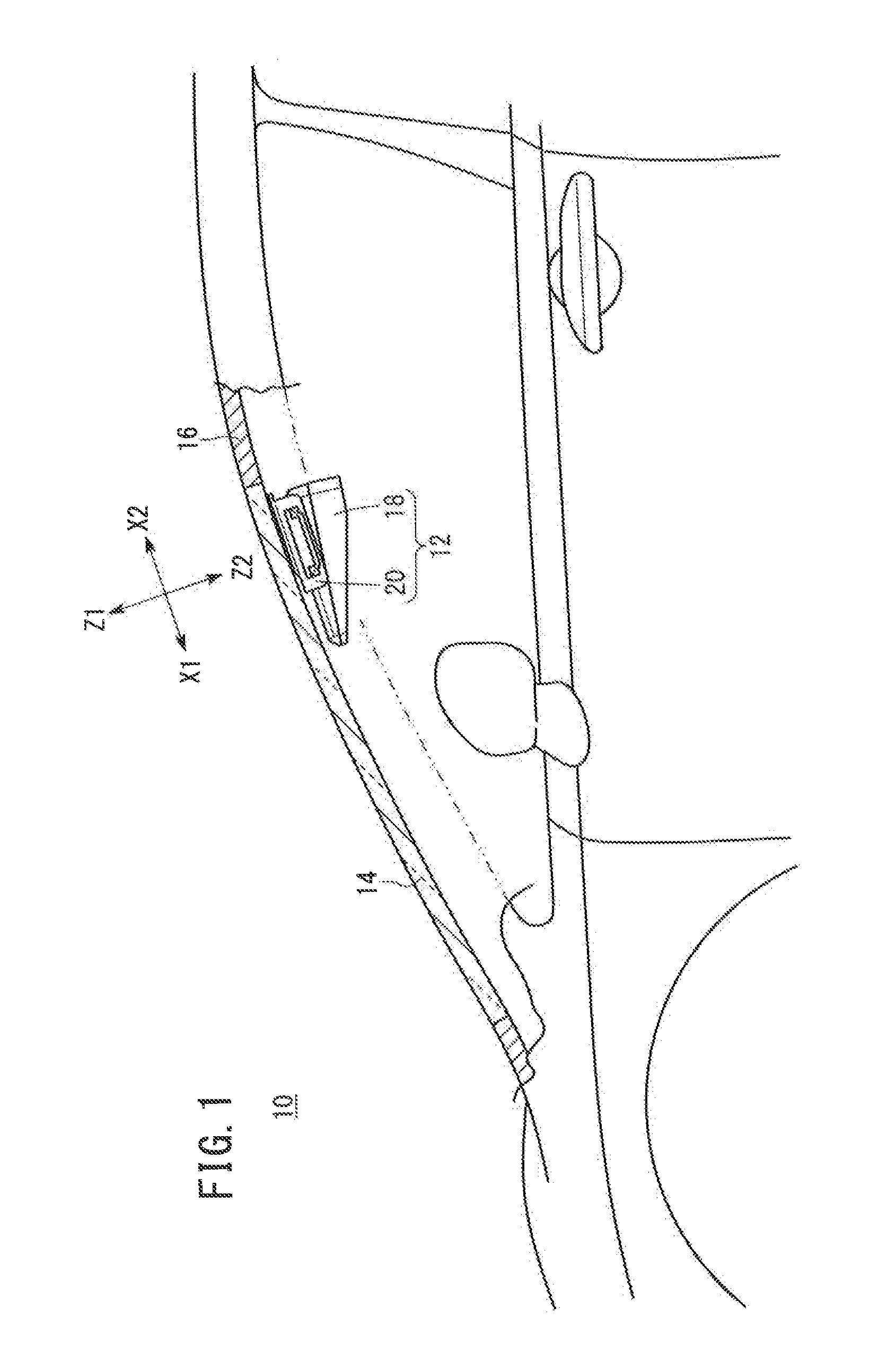
[0031]FIG. 1 is a schematic side elevational view showing a manner in which a camera unit 12 according to an embodiment of the present invention is mounted in position. As shown in FIG. 1, the camera unit 12 is mounted on a front windshield 14 of a vehicle 10. Alternatively, the camera unit 12 may be mounted on a roof 16 of the vehicle 10. The camera unit 12 is fixed in a position laterally of a rearview mirror, not shown.

[0032]According to the present embodiment, the camera unit 12 is used to detect a lane or to measure a distance for preventing the vehicle 10 from straying from the lane. However, as will be described in detail later, the camera unit 12 is not limited to such uses.

[1-2. Overall Structure]

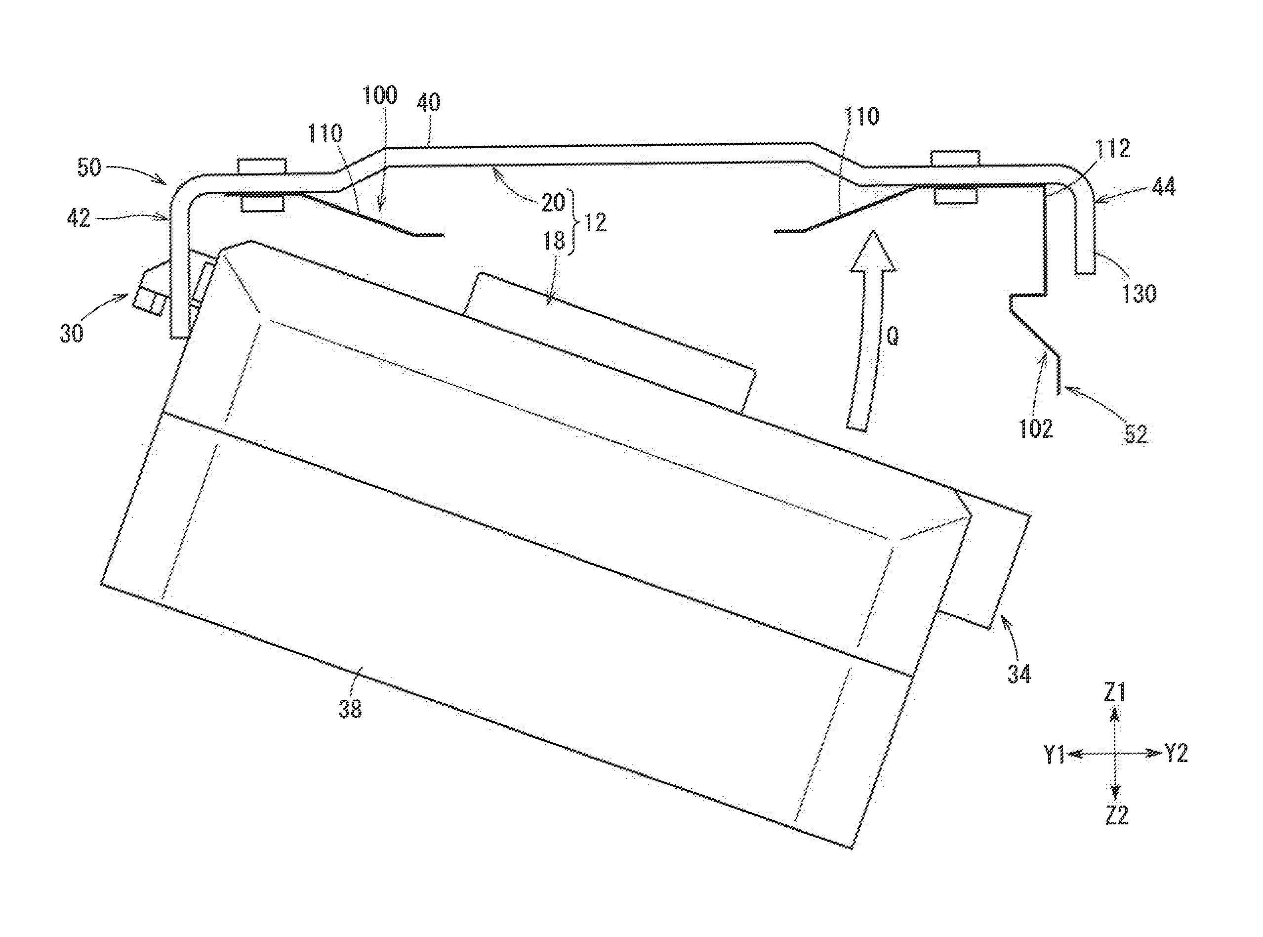
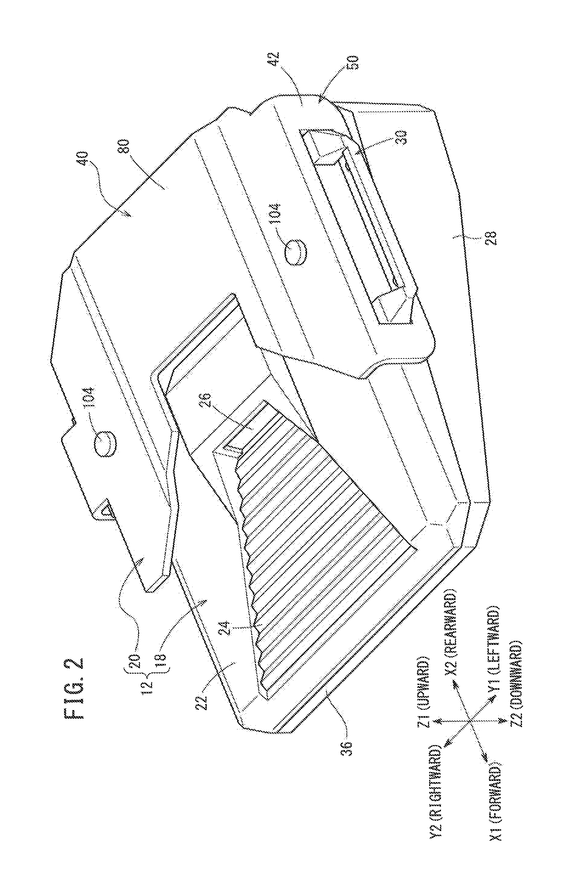
[0033]FIG. 2 is a perspective view of the camera unit 12 as viewed from a front-left-side-elevational-plan direction (X2-Y2-Z2 direction). FIG. 3 is a perspective view of the camera unit 12 as viewed from a front-ri...


PUM


Abstract

A camera unit increases the degree of freedom with which the camera unit can be designed. The camera unit includes a camera body having a hook held in hooked engagement with a bracket. The bracket includes a first support engaged by the hook and which supports the camera body in an angularly movable fashion, and a second support supporting the camera body that is secured to the second support.

Description

CROSS-REFERENCE TO RELATED APPLICATION[0001]This application is based upon and claims the benefit of priority from Japanese Patent Application No. 2013-152423 filed on Jul. 23, 2013, the contents of which are incorporated herein by reference.BACKGROUND OF THE INVENTION[0002]1. Field of the Invention[0003]The present invention relates to a camera unit having a camera body and a bracket for fixing the camera body, which is detachably supported on the bracket, to an object such as a vehicular front windshield, for example, on which the camera unit is installed.[0004]2. Description of the Related Art[0005]U.S. Patent Application Publication No. 2012 / 0099850 (hereinafter referred to as “US 2012 / 0099850 A1”) discloses a mounting structure, which enables a vehicle camera to be detachably mounted easily in place, and which makes it possible to position the mounted vehicle camera suitably (see paragraph [0005]). To achieve this object, the mounting structure disclosed in US 2012 / 0099850 A1 h...

Claims


Application Information

Patent Timeline
Patent Type & Authority Applications(United States)
IPC IPC(8): G03B17/56
CPCG03B17/561B60R11/04B60R2011/0026B60R2011/0063B60R2011/0071B60R2011/0077F16M11/041F16M13/00F16M13/02
Inventor MATORI, TADAHIRO
Owner HONDA MOTOR CO LTD
Why Eureka
Try Eureka