Compacting device for compacting container

a technology of compacting container and compacting device, which is applied in the direction of presses, presses, manufacturing tools, etc., can solve the problems of inability to return the receptacle to a non-compact state, and general unidimensional action of compacting apparatus, so as to reduce the risk of (excessive) destruction, advance efficiently, and reduce the speed of conveying

Active Publication Date: 2015-02-05
WINCOR NIXDORF INT
View PDF7 Cites 3 Cited by
  • Summary
  • Abstract
  • Description
  • Claims
  • Application Information

AI Technical Summary

Benefits of technology

[0019]One or more advancing devices are provided in each of the compacting unit and the post-compacting unit to ensure that the receptacle is advanced in the insertion direction and to transport the receptacle first through the compacting unit and then through the post-compacting unit. Since the positions of the at least one first advancing device of the compacting unit and the at least one second advancing device of the post-compacting unit are changeable with respect to one another in the insertion direction, a receptacle conveyed from the compacting unit to the post-compacting unit can be compressed between the compacting unit and the post-compacting unit. Thus, it is possible to run the at least one first advancing device of the compacting unit and the at least one second advancing device of the post-compacting unit for example at different speeds, such that a receptacle is conveyed for example more quickly by the compacting unit to the post-compacting unit than the post-compacting unit can discharge the receptacle. This has the effect that the receptacle is compressed between the compacting unit and the post-compacting unit, wherein, on account of the variability of the position of the at least one first advancing device and the at least second advancing device with respect to one another, the distance between the at least one first advancing device and the at least one second advancing device is changeable and thus the volume of a compression space located between the advancing devices is variable.
[0054]If the at least one (first or second) advancing device is configured as a chain drive, a piercing tool can be attached in each case to the individual chain links for example at regular intervals. In this case, provision can be made for a piercing tool to be arranged only on every second chain link on the at least one first advancing device, while a piercing tool is arranged on every chain link on the at least one second advancing device. The distance between the piercing tools on the at least one first advancing device is thus twice as large as the distance between the piercing tools on the at least one second advancing device. This has the advantageous effect that, although a receptacle is conveyed reliably into the compression space between the compacting unit and the post-compacting unit, it is not unduly destroyed during compression by the piercing tools of the first advancing devices. By means of the second advancing devices of the post-compacting unit, following compression, the compacted receptacle can then be discharged from the compression space, wherein, on account of the reduced conveying speed of the second advancing devices, the risk of (excessive) destruction of a receptacle and for example the occurrence of stress whitening is reduced.

Problems solved by technology

Secondly, in accordance with requirements for example of the Deutsche Pfandsystem GmbH (DPG), upon the return of receptacles the receptacle itself or check markings attached to the receptacle should be destroyed such that it is not possible to return the receptacle to a noncompacted state and thus to insert the receptacle into a reverse vending machine again.
The compacting apparatus acts in this case unidimensionally in that the receptacle is conveyed between the diametrically opposed advancing devices.
Such compacting apparatuses generally act unidimensionally, in that receptacles are pressed flat in one spatial direction and in the process are destroyed.
This results in a comparatively complicated multistage construction with a considerable installation space requirement.
In addition, in conventional compacting apparatuses, as a result of the manner of destruction of the receptacle during compacting, sharp corners and edges frequently form on compacted receptacles, these sharp corners and edges having the effect that receptacles catch on and interlock with one another in a container into which the receptacles are introduced, this resulting in an unfavorable bulk handling and layering behavior with the result that compacted receptacles cannot readily be distributed favorably in a container.

Method used


Image

  • Compacting device for compacting container
  • Compacting device for compacting container
  • Compacting device for compacting container

Examples


Embodiment Construction

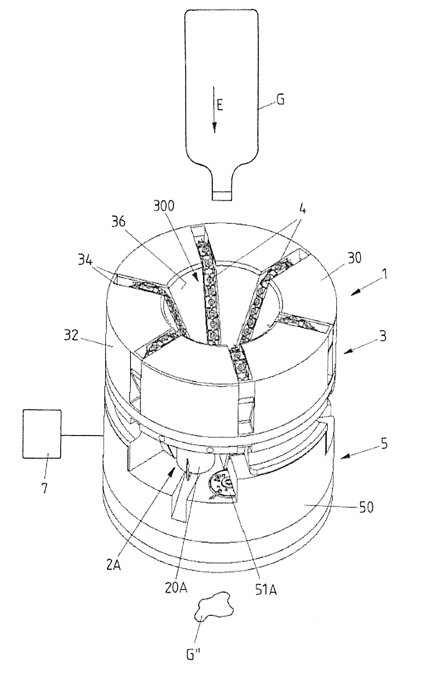
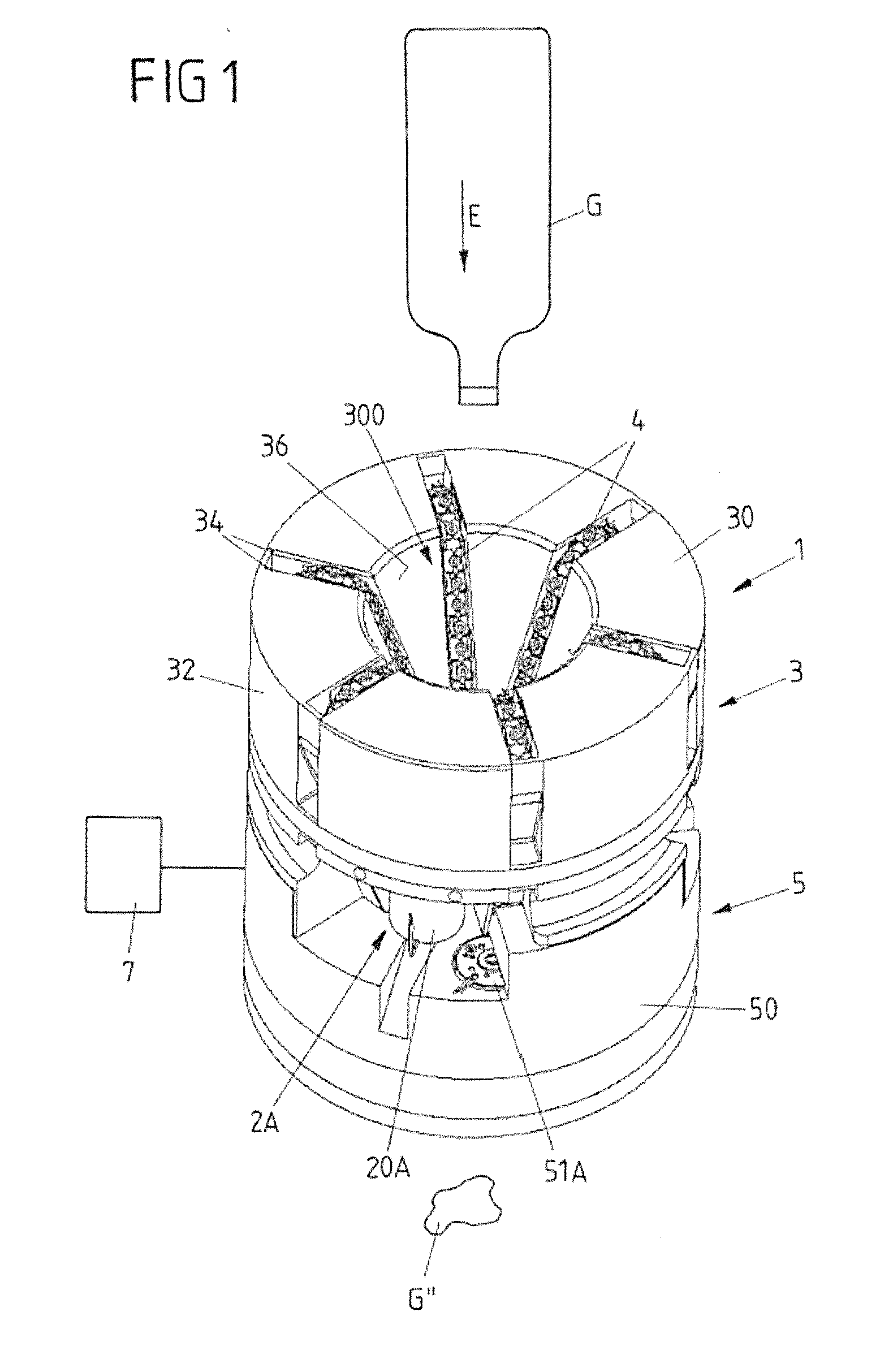
[0083]FIGS. 1 to 13 show an exemplary embodiment of a compacting apparatus 1 which has a compacting unit 3 for conveying a receptacle G in an insertion direction E and for compacting the receptacle G in the compacting unit 3, and a post-compacting unit 5, arranged downstream of the compacting unit 3 in the insertion direction E, for compacting the receptacle G further.

[0084]The compacting unit 3 and the post-compacting unit 5 realize different units which interact to compact a receptacle G.

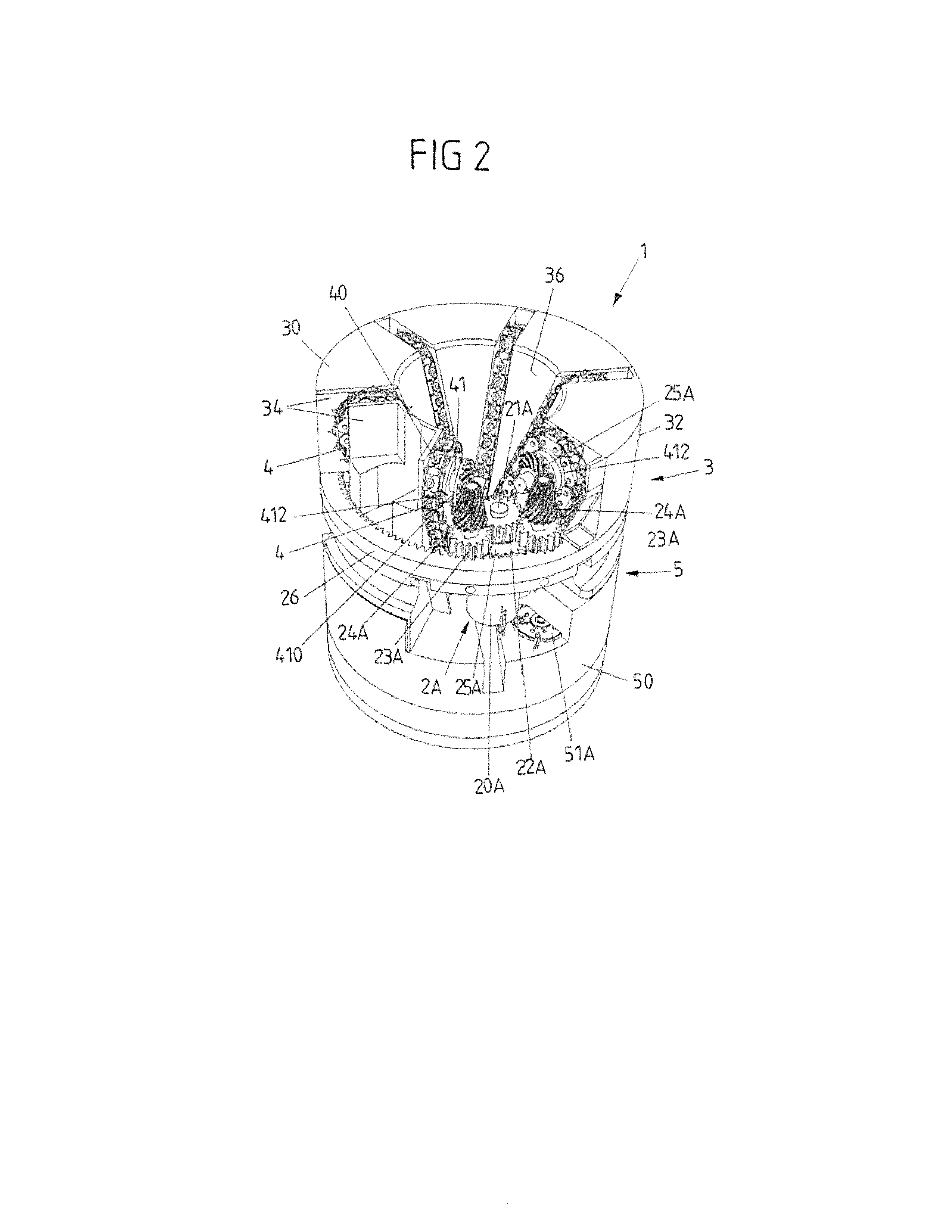
[0085]The compacting unit 3 has six advancing devices 4 which are formed by chain drives 40 (see FIGS. 1 and 2). The chain drives 40 are mounted on bearing plates 34 of a housing 32 via sprockets 412 and have chains that are formed from chain links 400 and are arranged on the sprockets 412. Together with guide surfaces 36, the chain drives 40 form a hopper and are intended to be driven such that a receptacle G can be inserted into the hopper through an insertion opening 300 in order to be conveyed...


PUM


Abstract

A compacting apparatus (1) for compacting receptacles has a compacting unit (3) with at least one first advancing device (4) for transporting at least one receptacle (G) in an insertion direction (E). The compacting unit (3) is configured to compact the receptacle (G) while the receptacle (G) is transported in the insertion direction (E). A post-compacting unit (5) is downstream of the compacting unit (3) in the insertion direction (E) and has at least one second advancing device (6) for transporting the at least one receptacle (G) through the post-compacting unit (5). The post-compacting unit (5) is configured to compact the at least one receptacle (G) further. Positions of the at least one first advancing device (4) of the compacting unit (3) and the at least one second advancing device (6) of the post-compacting unit (5) are changeable with respect to one another in the insertion direction (E).

Description

BACKGROUND[0001]1. Field of the Invention[0002]The invention relates to a compacting apparatus for compacting receptacles.[0003]2. Description of the Related Art[0004]A compacting apparatus for compacting receptacles comprises a compacting unit which has at least one first advancing device for transporting at least one receptacle in an insertion direction. The compacting unit is configured to compact the at least one receptacle while it is being transported in the insertion direction. The compacting apparatus further comprises a post-compacting unit arranged downstream of the compacting unit in the insertion direction, said post-compacting unit having at least one second advancing device for transporting the at least one receptacle through the post-compacting unit, wherein the post-compacting unit is configured to compact the at least one receptacle further.[0005]Such a receptacle may be for example a disposable plastics bottle (such as a PE or PET bottle) or a beverage can.[0006]A ...

Claims


Application Information

Patent Timeline
Patent Type & Authority Applications(United States)
IPC IPC(8): B30B9/32B30B12/00B30B15/30B30B1/30
CPCB30B9/321B30B15/30B30B12/00B30B1/30B30B9/325Y10S100/902B30B15/068B30B15/32
Inventor HARTUNG, DOMENIC
Owner WINCOR NIXDORF INT
Why Eureka
Try Eureka