Thermal head printer and printing method in thermal head printer

a printing method and printer technology, applied in the field of thermal head printers and printing methods in thermal head printers, can solve the problems of uneven density distribution, increased production costs, and increased production costs, and achieve the effects of reducing the conveying speed of the recording medium, reducing the density of the printed image, and high ra

Inactive Publication Date: 2008-04-01
SONY CORP
View PDF5 Cites 7 Cited by
  • Summary
  • Abstract
  • Description
  • Claims
  • Application Information

AI Technical Summary

Benefits of technology

[0009]Consequently, since the heat generated for the printing operation remains stored in the thermal head, if the subsequent cooling process is insufficient, the protective film may expand or may be subject to a change in its physical properties. This may cause the protective film to damage as a result of friction between the protective film and the ink ribbon. If the protective film is damaged to a large degree, the print face may be subject to scratches or it may be difficult to sufficiently transmit the heat generated by the heating resistors to the ink ribbon, thus resulting in a reduced print density.
[0011]A technique for increasing the print speed while solving problems, such as a tailing phenomenon, an uneven density distribution, and damaging of the protective film, is known. Specifically, this is achieved by lowering the peak temperature of the heating resistors. For example, Japanese Unexamined Patent Application Publication No. 63-295278 discloses a thermal head printer that controls the electricity applied to the heating resistors on the basis of print history so as to prevent heat from remaining in the thermal head.
[0012]According to Japanese Unexamined Patent Application Publication No. 63-295278, the time in which high voltage is applied to the heating resistors is shortened by performing both pulse-width control and voltage control on the basis of print history. Consequently, this enhances the durability of the heating resistors and provides a thermal head printer that allows for relatively high-speed printing.
[0015]Likewise, if the print history includes an image taken in the daytime, the printing operation is performed at a speed for a daytime image even if the image to be printed is a nighttime image. Therefore, the heating values of the heating resistors are increased to correspond to the high print density, thus leading to a shorter lifespan of the protective film. On the other hand, to prepare for a nighttime image, the heating values of the heating resistors may be preliminarily reduced so as to prevent the lifespan of the protective film from being shortened. However, this means that the print speed will constantly be limited, and thus inhibits the improvement of the print speed.
[0016]Therefore, it is desirable to provide a thermal head printer and a printing method in a thermal head printer that prevent damaging of, for example, a protective film to achieve a longer lifespan of a thermal head, that solve problems, such as scratches on a print face, a reduced print density, a tailing phenomenon, and an uneven density distribution, and that achieve a significantly-enhanced print speed.
[0023]Furthermore, if the heating values of the heating element are limited while the conveying speed of the recording medium is kept at a high rate, the density of the printed image may possibly become lower. Therefore, the heating-value controller preferably limits the heating values of the heating element by reducing the conveying speed of the recording medium.

Problems solved by technology

However, even when the printing operation is completed, if the heat generated for the printing operation remains stored in the thermal head and if the subsequent cooling process is insufficient, the printing paper may be subject to a so-called tailing phenomenon in which a tail-like mark is formed on the print face, or the printed image may be subject to, for example, an uneven density distribution.
Consequently, since the heat generated for the printing operation remains stored in the thermal head, if the subsequent cooling process is insufficient, the protective film may expand or may be subject to a change in its physical properties.
This may cause the protective film to damage as a result of friction between the protective film and the ink ribbon.
If the protective film is damaged to a large degree, the print face may be subject to scratches or it may be difficult to sufficiently transmit the heat generated by the heating resistors to the ink ribbon, thus resulting in a reduced print density.

Method used


Image

  • Thermal head printer and printing method in thermal head printer
  • Thermal head printer and printing method in thermal head printer
  • Thermal head printer and printing method in thermal head printer

Examples


Embodiment Construction

[0032]Embodiments of the present invention will now be described with reference to the drawings.

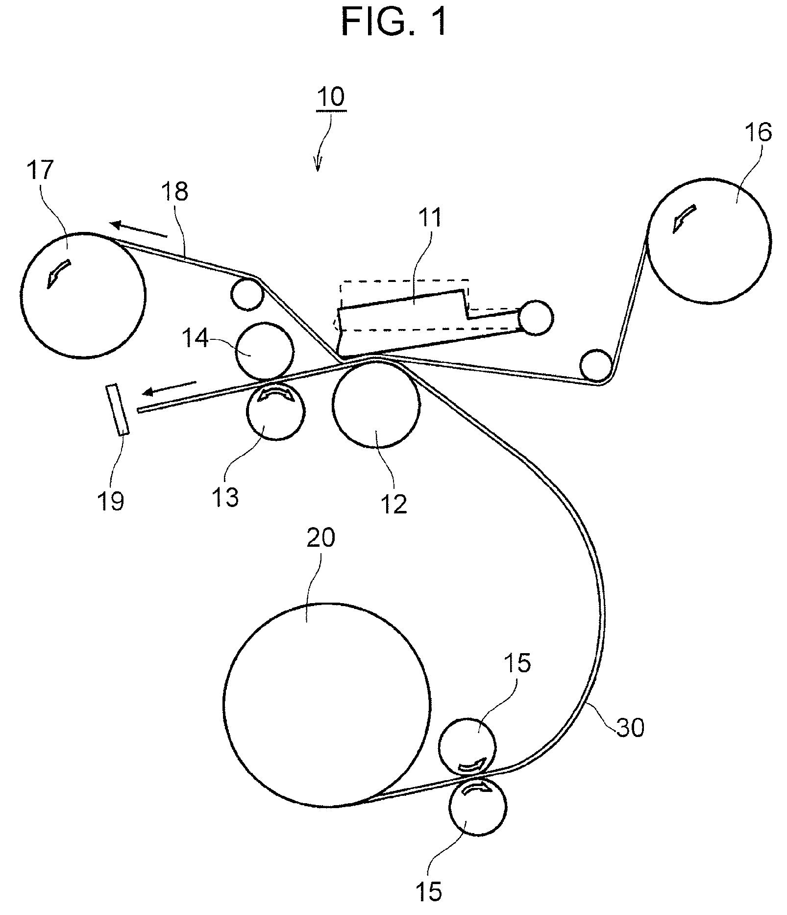
[0033]FIG. 1 is a side view showing a relevant portion of a thermal head printer 10 according to an embodiment of the present invention.

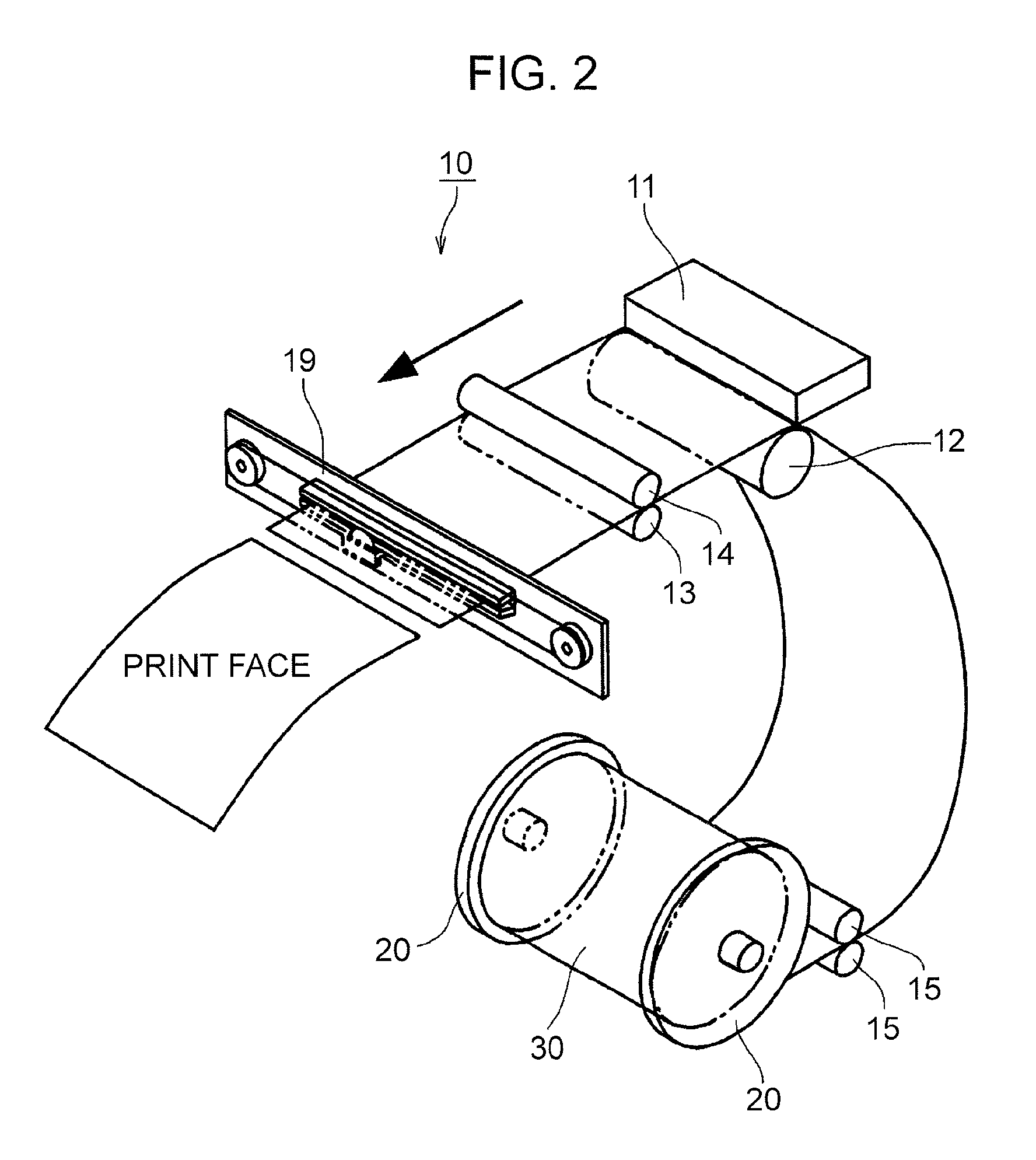
[0034]FIG. 2 is a perspective view showing a relevant portion of the thermal head printer 10 according to this embodiment. In FIG. 2, ink ribbons provided in the thermal head printer 10 are not shown.

[0035]The thermal head printer 10 shown in FIGS. 1 and 2 is provided with a dye-sublimation thermal head 11. Roll paper 30 serving as a recording medium is loadable in the thermal head printer 10. The thermal head 11 has a plurality of linearly-arranged heating resistors serving as heating elements. The thermal head printer 10 performs a printing operation by utilizing thermal energy generated in response to electricity applied to the heating resistors so as to transfer dry ink provided on an ink ribbon 18 shown in FIG. 1 onto the roll paper 30. If the therma...


PUM


Abstract

A thermal head printer includes a platen, a thermal head having a heating element, a heating-value arithmetic unit, a heating-value comparator, an excess-value counter, and a heating-value controller. The thermal head printer performs a printing operation by conveying a recording medium between the platen and the thermal head and heating the heating element on the basis of image data to be printed. The heating-value arithmetic unit calculates heating values for the heating element corresponding to the image data. The heating-value comparator compares each calculated heating value with a reference heating value of the heating element. The excess-value counter counts the number of calculated heating values that exceed the reference heating value so as to determine an excess-value number. The heating-value controller limits the heating values of the heating element if the excess-value number exceeds a reference number.

Description

CROSS REFERENCES TO RELATED APPLICATIONS[0001]The present invention contains subject matter related to Japanese Patent Application JP 2005-075733 filed in the Japanese Patent Office on Mar. 16, 2005, the entire contents of which are incorporated herein by reference.BACKGROUND OF THE INVENTION[0002]1. Field of the Invention[0003]The present invention relates to thermal head printers and printing methods in thermal head printers for performing a printing operation by utilizing thermal energy generated in response to electricity applied to heating elements. In particular, the present invention relates to a thermal head printer and a printing method in a thermal head printer achieving both a higher print speed and longer lifespan.[0004]2. Description of the Related Art[0005]Known printing types of thermal head printers mainly include a dye-sublimation type, a thermal-wax type, and a thermal-recording type. These types of thermal head printers are provided with a line thermal head having...

Claims


Application Information

Patent Timeline
Patent Type & Authority Patents(United States)
IPC IPC(8): B41J2/36
CPCB41J2/375A47J47/14
Inventor TAKANO, HIROAKITAKIZAWA, NAOKIKATO, SHINJIHORII, AKIHIRO
Owner SONY CORP
Why Eureka
Try Eureka