Method and machine for treating textile fabrics with an adjustable air flow

An adjustable, air-treating technology, used in textiles and papermaking, liquid/gas/vapor jet-propulsion fabrics, thin material processing, etc., can solve problems such as reducing the strength of impact, and achieve the effect of reducing strength

Active Publication Date: 2017-02-22
BIANCALANI SRL
View PDF4 Cites 7 Cited by
  • Summary
  • Abstract
  • Description
  • Claims
  • Application Information

AI Technical Summary

Problems solved by technology

[0009] The last mentioned machines, while allowing to obtain a lower frequency of fabric impingement grids, do not allow reducing the intensity of the impingement without reducing the flow and drying speed

Method used


Image

  • Method and machine for treating textile fabrics with an adjustable air flow
  • Method and machine for treating textile fabrics with an adjustable air flow
  • Method and machine for treating textile fabrics with an adjustable air flow

Examples


Embodiment Construction

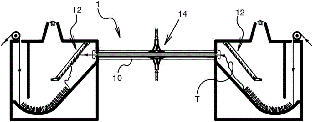
[0025] figure 1 Shows a schematic longitudinal section through a continuous open diverter 1 equipped with a channel 10 of rectangular section for pneumatically conveying the fabric T and equipped with an impingement grid 12 facing the opening of the channel .

[0026] A system 14 for injecting air into the channel is located approximately in the middle of the channel 10 and generally above and below the fabric. The gas flow is produced by means of per se known type not shown.

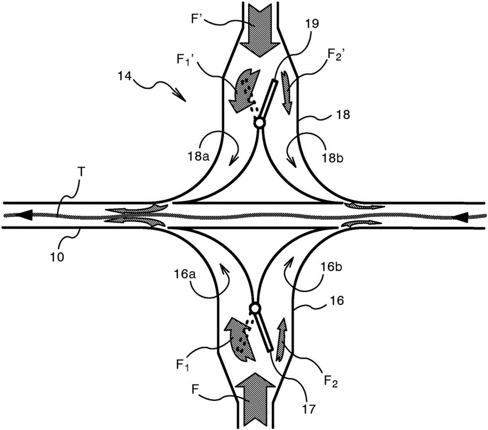
[0027] The system 14 - in figure 2 shown in enlarged and more detailed manner in -comprising two directional valves 16, 18 each having two passages 16a, 16b and 18a, 18b, the passages 16a, 16b and 18a, 18b are suitably oriented to direct airflow into the channel in one direction or the other.

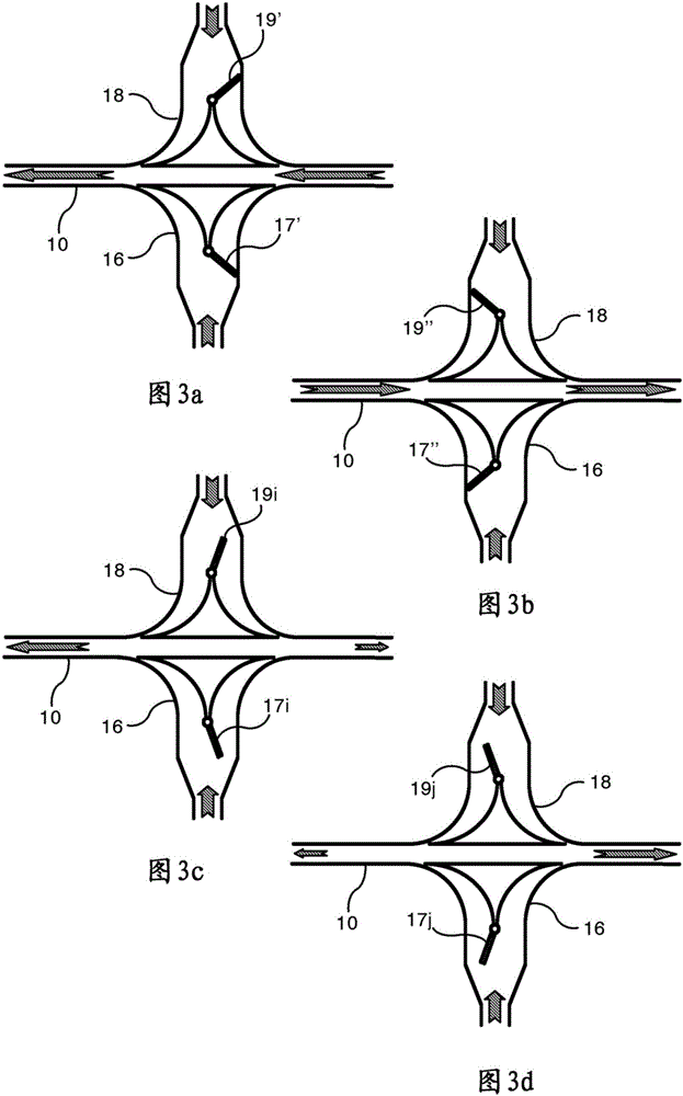
[0028] According to the invention, each valve also comprises an adjustable flap 17, 19 adapted to completely or partially close the inlets to the passages 16a, 16b and 18a, 18b.

[0029] Thus, the valves 16...


PUM


Abstract

A machine for treating a fabric (T) with air, comprises a tunnel (10) for pneumatically transporting the fabric and means for injecting the air into the tunnel above and / or below the fabric and comprising at least one diverting valve (16; 18) located substantially half way along the tunnel and having two channels (16a, 16b; 18a, 18b) which are oriented to direct the air flow entering the tunnel in one direction or the other. The valve comprises an adjustable baffle (17; 19) adapted to shut off access to the channels (16a, 16b; 18a, 18b) either wholly or partly. In the treatment method of the invention, the air flow (F;F') entering the tunnel is divided into two unequal components (F1, F2; F1', F2') directed towards opposite ends of the tunnel.

Description

technical field [0001] The present invention relates to a method and a machine for treating textile fabrics by adjustable air flow. Background technique [0002] In the post-processing of woven fabrics, it is common practice to use continuous open width machines (diverters) to process the fabrics to obtain fiber expansion and a soft and comfortable hand of all kinds of fabrics. [0003] These machines comprise straight air channels and at least one deflector baffle movable between two extreme positions to alternately channel all the air into the channels in one direction or the other. [0004] In this way the fabric is conveyed at high speed towards one or the other of the channel openings and is transferred alternately to one or the other of the two piles of fabric at both ends of the channel. [0005] Impingement grids, suitably positioned in front of the two openings of the delivery channel, stop the fabric while allowing air to continue to flow towards the two hoods abo...

Claims


Application Information

Patent Timeline
Patent Type & Authority Applications(China)
IPC IPC(8): D06B3/28D06C19/00
CPCD06C19/00B65H20/14F26B13/103D06B3/28
Inventor 马西莫·比安卡拉尼里卡尔多·拉瓦利
Owner BIANCALANI SRL
Why Eureka
Try Eureka