

Communication control method
- Summary
- Abstract
- Description
- Claims
- Application Information
AI Technical Summary
Benefits of technology
Problems solved by technology
Method used
Image

Examples
embodiment
Overview of Embodiment
[0032]A communication control method of the first embodiment is a communication control method in a relay station that holds a donor base station list, is connected to a donor base station existing on the donor base station list, and performs relay transmission between the donor base station and a user terminal, and comprises a step A of designating a neighboring base station, a step B of inquiring the neighboring base station designated in the step A of whether to accept or refuse the relay station, and a step C of updating the donor base station list in response to an inquiry result in the step B.
[0033]In the first embodiment, the step B may comprise a step B1 of inquiring the neighboring base station designated in the step A of whether the neighboring base station has a donor base station function.
[0034]In the first embodiment, the step B may comprise a step B2 of notifying the neighboring base station designated in the step A of a load state of the relay st...
first embodiment
(1) First Embodiment
[0054]In the present embodiment, an example of a mobile communication system configured on the basis of 3GPP standards (that is, LTE-Advanced) after release 10 will be described.
[0055](1.1) Overview of the Mobile Communications System
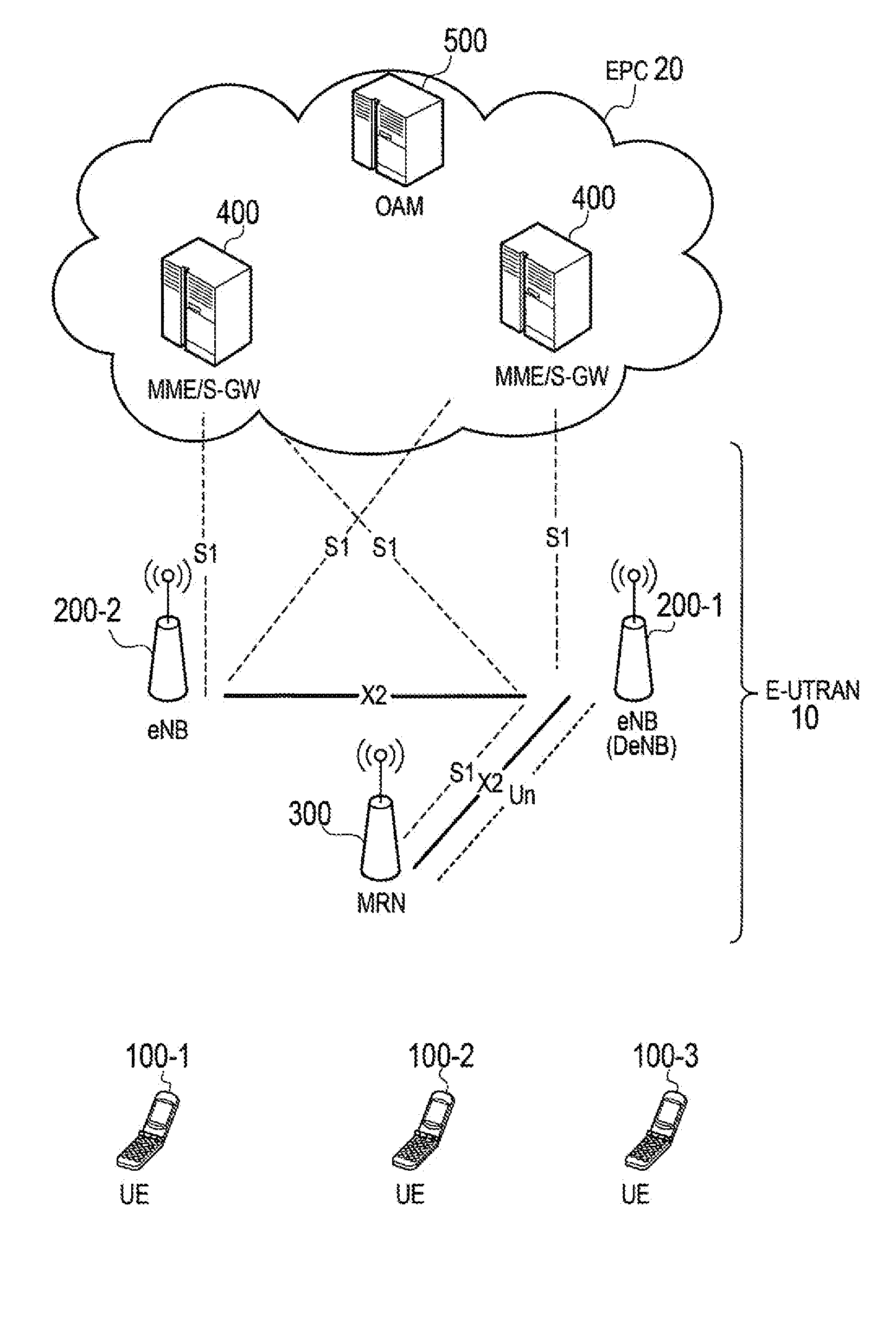
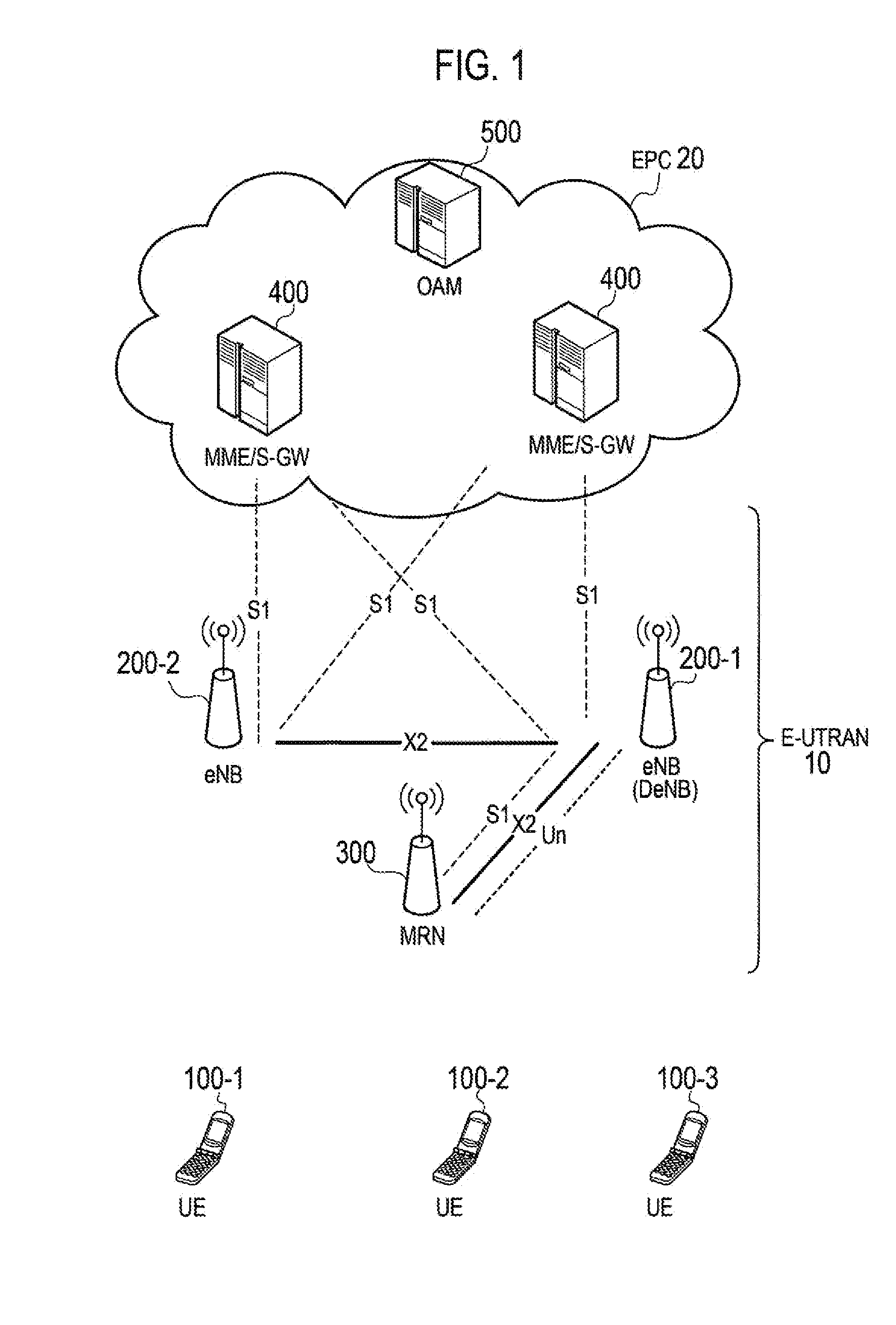
[0056]FIG. 1 is a configuration diagram of a mobile communication system according to the present embodiment. As illustrated in FIG. 1, the mobile communication system includes a user terminal (UE: User Equipment) 100, a base station (eNB: evolved Node-B) 200, a movable relay station (MRN: Mobile Relay Node) 300, a mobility management device (MME: Mobility Management Entity) / a gateway device (S-GW: Serving Gateway) 400, and an operation and maintenance device (OAM: Operation and Maintenance) 500.
[0057]The eNB 200 and the MRN 300 are network devices included in a radio access network (E-UTRAN: Evolved-UMTS Terrestrial Radio Access Network) 10. The MME / S-GW 400 and the OAM 500 are network devices included in a core network (EPC: Evolve...
second embodiment
(2) Second Embodiment
[0164]Hereinafter, the second embodiment will be described while focusing on the differences from the aforementioned first embodiment.
[0165]In the present embodiment, an operation when the MRN 300 performs handover using the aforementioned DeNB list will be mainly described.
[0166](2.1) Operation According to Second Embodiment
[0167]Hereinafter, the operation of the mobile communication system according to the present embodiment will be described.
[0168]In the following operation patterns 1 to 4, in a mobile communication system in which the eNB 200 performs determination regarding the handover of the UE 100 connected to the eNB 200, the MRN 300, which is connected to the DeNB 200-1 and performs relay transmission between the DeNB 200-1 and the UE 100, performs determination regarding the handover of the MRN 300. Then, the MRN 300 transmits a handover request to a target eNB 200 using the X2 interface that is established between the MRN 300 and the target eNB 200.
[...
PUM
 Abstract
Description
Claims
Application Information