High voltage hybrid polymeric-ceramic dielectric capacitor

a dielectric capacitor and polymer technology, applied in the direction of fixed capacitors, fixed capacitor dielectrics, fixed capacitor details, etc., can solve the problems of achieving the desired fabrication cost of the integrated circuit while meeting the protection and reliability goals

Active Publication Date: 2015-02-12
TEXAS INSTR INC
View PDF5 Cites 6 Cited by
  • Summary
  • Abstract
  • Description
  • Claims
  • Application Information

AI Technical Summary

Problems solved by technology

It may further be desirable to integrate the isolation component into the integrated circuit, but meeting the protection and reliability goals while attaining a desired fabrication cost of the integrated circuit may be problematic.

Method used


Image

  • High voltage hybrid polymeric-ceramic dielectric capacitor
  • High voltage hybrid polymeric-ceramic dielectric capacitor
  • High voltage hybrid polymeric-ceramic dielectric capacitor

Examples


Embodiment Construction

[0009]The following co-pending patent application contains related material and is hereby incorporated by reference: U.S. patent application 12 / ______ (Texas Instruments docket number TI-72812, filed concurrently with this application).

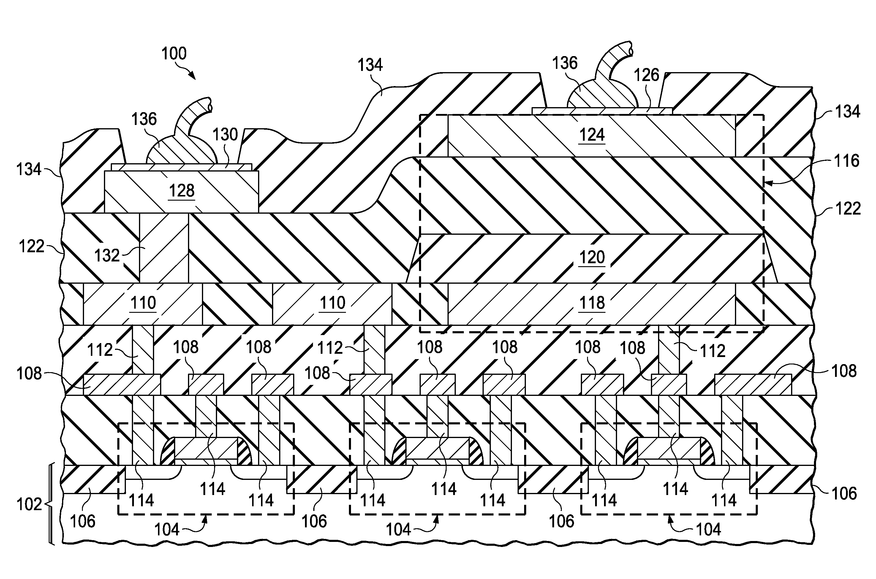
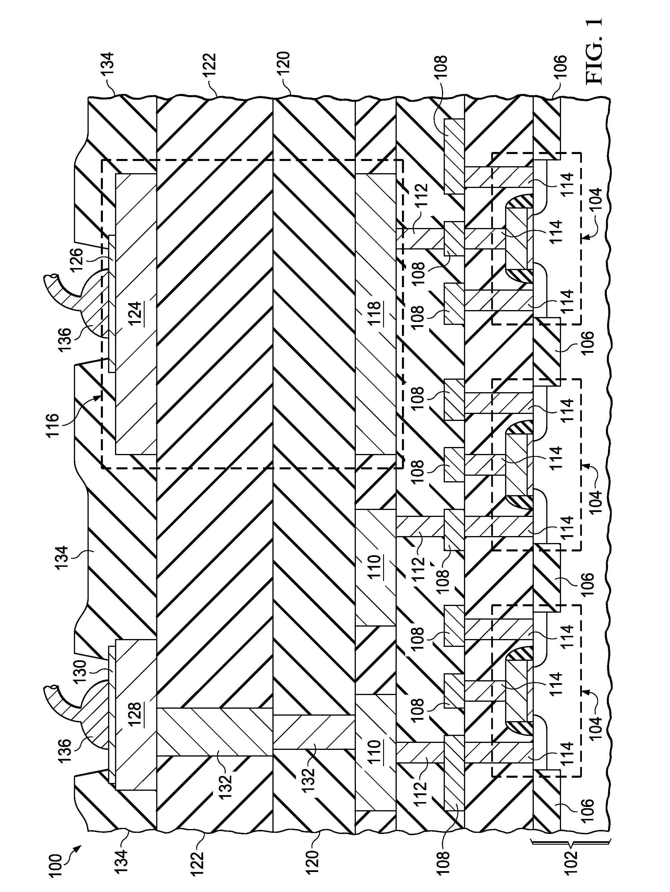
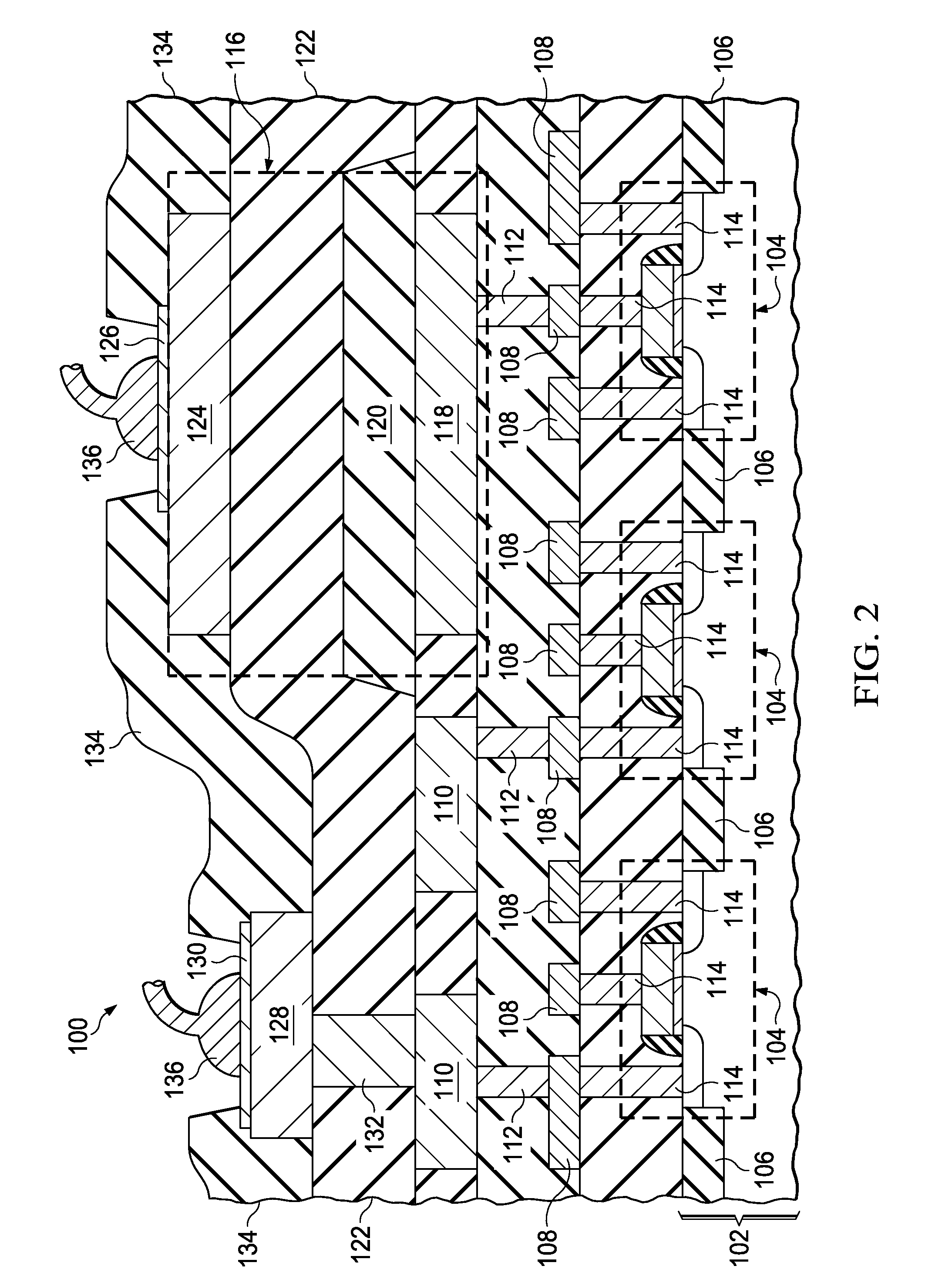
[0010]The present invention is described with reference to the attached figures. The figures are not drawn to scale and they are provided merely to illustrate the invention. Several aspects of the invention are described below with reference to example applications for illustration. It should be understood that numerous specific details, relationships, and methods are set forth to provide an understanding of the invention. One skilled in the relevant art, however, will readily recognize that the invention can be practiced without one or more of the specific details or with other methods. In other instances, well-known structures or operations are not shown in detail to avoid obscuring the invention. The present invention is not limited by the illustra...


PUM


Abstract

An integrated circuit includes isolation capacitors which include a silicon dioxide dielectric layer and a polymer dielectric layer over the layer of silicon dioxide. The silicon dioxide dielectric layer and the polymer dielectric layer extend across the integrated circuit. Top plates of the isolation capacitors have bond pads for wire bonds or bump bonds. Bottom plates of the isolation capacitors are connected to components of the integrated circuit. Other bond pads are connected to components in the integrated circuit through vias through the silicon dioxide dielectric layer and the polymer dielectric layer.

Description

CROSS REFERENCE TO RELATED APPLICATIONS[0001]This application is a divisional of U.S. Nonprovisional patent application Ser. No. 13 / 960,344, filed Aug. 6, 2013, the contents of which are herein incorporated by reference in its entirety.FIELD OF THE INVENTION[0002]This invention relates to the field of integrated circuits. More particularly, this invention relates to high voltage capacitors in integrated circuits.BACKGROUND OF THE INVENTION[0003]An integrated circuit may receive input signals which have direct current (DC) bias levels that are, for example, several hundred volts above the operating voltage for the integrated circuit, necessitating isolation components between the input signals and components such as transistors in the integrated circuit. It may be desirable for the isolation component to provide transient protection and surge protection of several thousand volts, as well as long term reliability. It may further be desirable to integrate the isolation component into t...

Claims


Application Information

Patent Timeline
Patent Type & Authority Applications(United States)
IPC IPC(8): H01L49/02H01L21/768H01L29/06
CPCH01L28/60H01L29/0642H01L23/5223H01L21/76877H01L23/5222H01L21/76802H01L24/05H01L24/06H01L2224/0603H01L2224/48463H01L2224/04042H01L2924/13091H01L2224/02166H01L2224/05093H01G4/14H01G4/10H01G4/206H01L28/40H01L2224/06102H01L2924/00H01L27/0288
Inventor BONIFIELD, THOMAS DYERWILLIAMS, BYRONJAGANATHAN, SHRINIVASAN
Owner TEXAS INSTR INC
Why Eureka
Try Eureka