Extruder

Active Publication Date: 2015-02-12
LEISTRITZ EXTRUSIONSTECHN
View PDF1 Cites 10 Cited by
  • Summary
  • Abstract
  • Description
  • Claims
  • Application Information

AI Technical Summary

Benefits of technology

[0026]It may be furthermore provided according to the method that the controller installation, simultaneously with or immediately after opening the clutch, activates a frequency inverter in order to reduce th

Problems solved by technology

An overload may thus already exist with the screw shafts but not be applied yet to the clutch.
This may have d

Method used


Image

  • Extruder
  • Extruder

Examples


Embodiment Construction

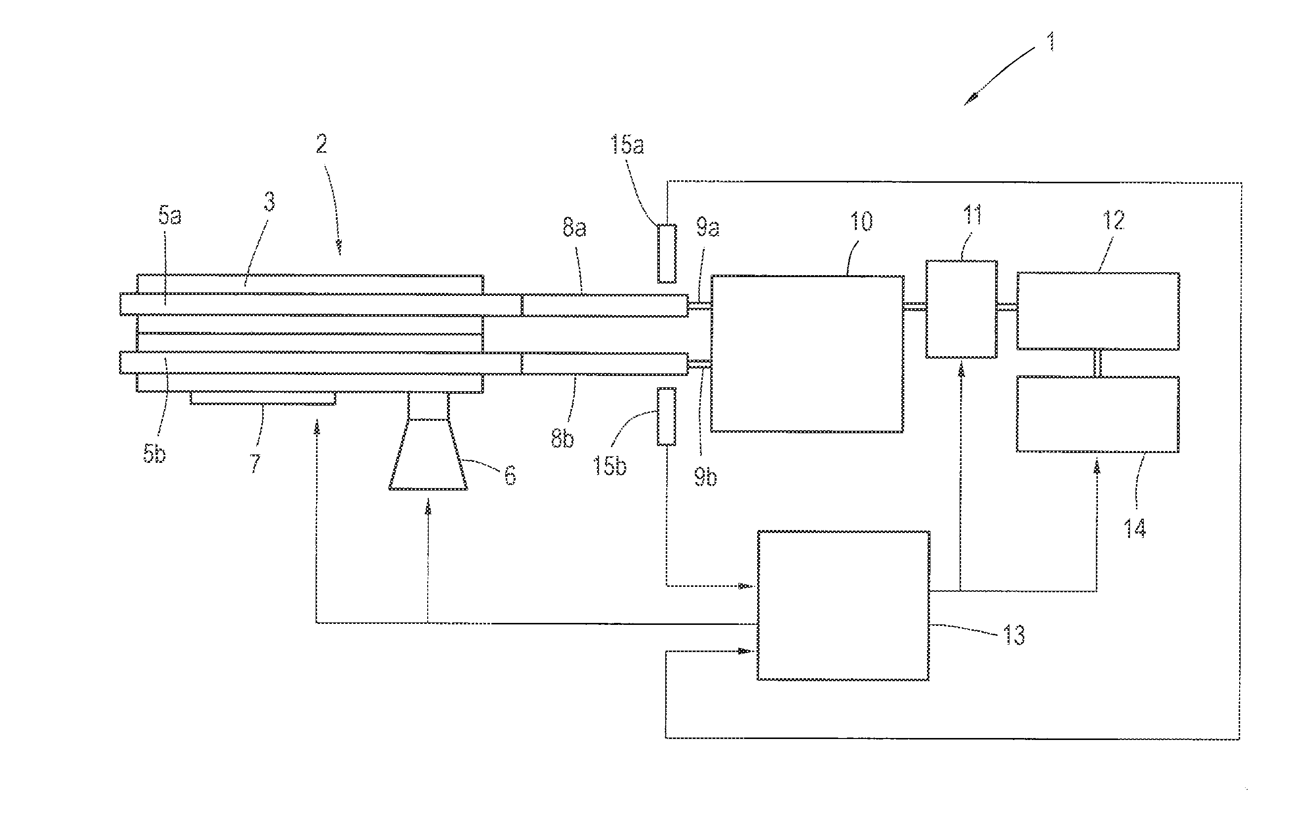
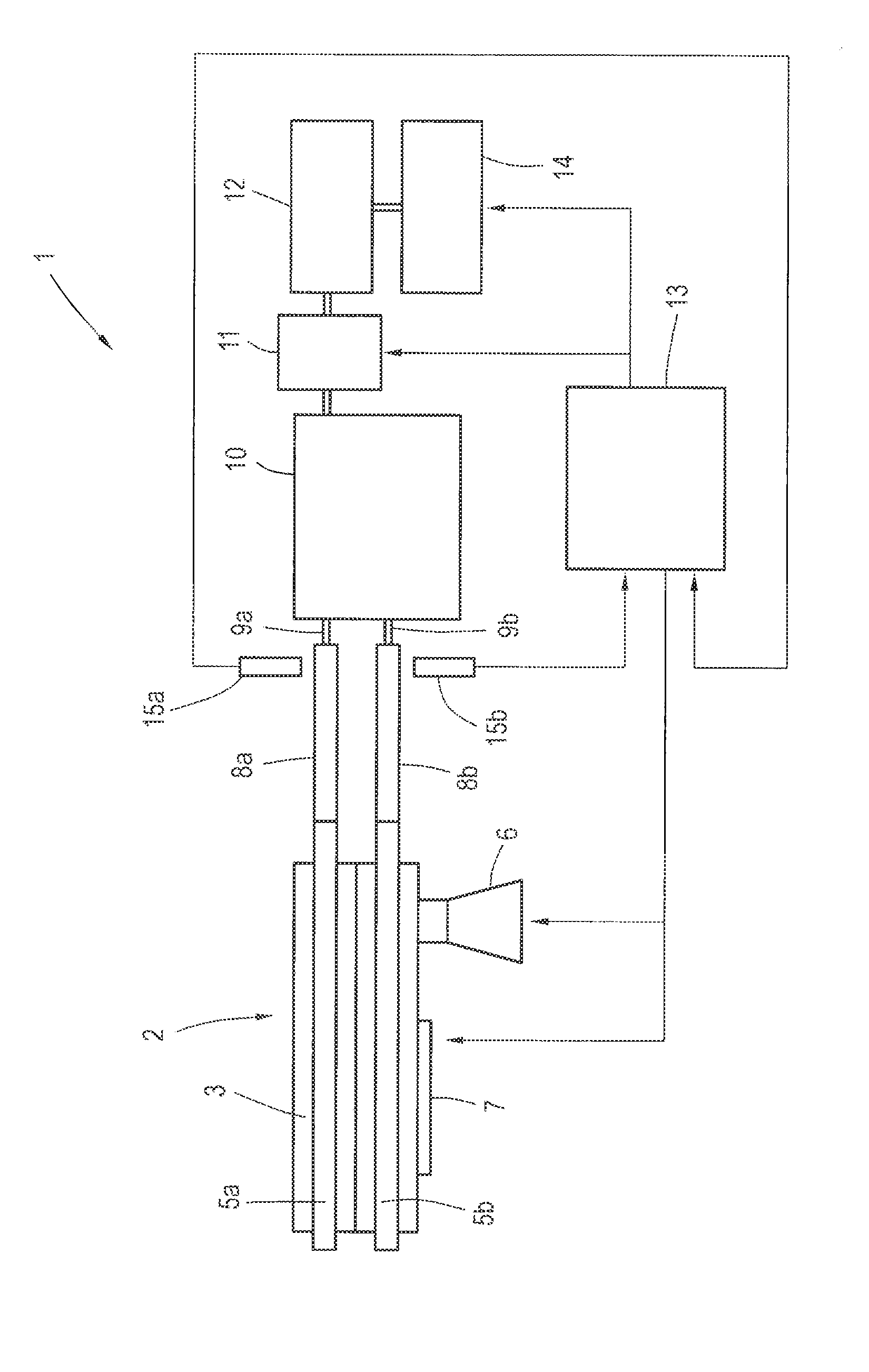
[0030]In the figure, an in-principle illustration of an extruder 1 according to the invention is shown, comprising an operative unit 2 having a cylinder 3 which, as is usual in most cases, is composed of a plurality of individual cylinder segments which are lined up next to one another and interconnected. As is shown in a highlighted manner here, two screw shafts 5a, 5b are rotatably accommodated in the cylinder 3. To this end, the cylinder 3 has a cylinder bore which is implemented as a figure-eight barrel bore, as is known per se.

[0031]In an exemplary manner, a further installation in the form of an infeed installation 6 is disposed on, or assigned to, respectively, the operative unit 2, wherein, of course, a plurality of such infeed installations 6 may also be provided. The material(s) to be processed is / are added via the infeed installation 6. Furthermore provided is a heating installation 7 via which the cylinder 3 can be temperature-controlled and which is also indicated in on...


PUM

PropertyMeasurementUnit
Magnetic fieldaaaaaaaaaa
Magnetizationaaaaaaaaaa
Torqueaaaaaaaaaa

Abstract

An extruder having an operative unit composed of a cylinder and at least two screw shafts which are rotatably accommodated therein, a gear unit having at least two output shafts, wherein each output shaft, via a connecting element, is connected in a rotationally fixed manner to one screw shaft, a motor which drives the gear unit and is coupled to the gear unit via a clutch, and a controller installation, wherein each connecting element or each output shaft is assigned a separate measuring installation for determining the applied torque, wherein the measuring installations communicate with the controller installation which, depending on the individual determined torques, controls the clutch which is implemented as a switchable clutch, wherein the controller installation is configured for opening the clutch both when a determined torque exceeds a torque limit value and also when the difference between the two determined torques exceeds a limit value.

Description

[0001]The present application claims priority of DE 10 2013 108 629.2, filed Aug. 9, 2013, the priority of this application is hereby claimed and this application is incorporated herein by reference.BACKGROUND OF THE INVENTION[0002]The invention relates to an extruder comprising an operative unit composed of a cylinder and at least two screw shafts which are rotatably accommodated therein, a gear unit having at least two output shafts, wherein each output shaft, via a connecting element, is connected in a rotationally fixed manner to one screw shaft, a motor which drives the gear unit and is coupled to the gear unit via a clutch, and a controller installation.[0003]As is known, extruders of this type serve for preparing compounds which, in the operative unit or the cylinder, respectively, are processed via one or more screw shafts, also referred to as extruder screws, rotating therein. In only an exemplary manner, mention may be made of plastic compounds which are melted and compoun...

Claims


Application Information

Patent Timeline
IPC IPC(8): B29C47/08F16H1/22B29C48/40B29C48/92B29C48/96
CPCF16H1/22B29C47/0805B29C48/92B29C48/252B29C48/2526B29C48/40B29B7/48B29B7/728B29C2948/92038B29C2948/92533B29C2948/92457B29C2948/92952
Inventor RECHTER, FRANKWOLF, SVEN
Owner LEISTRITZ EXTRUSIONSTECHN
Why Eureka
Try Eureka