Vehicle traction device and vehicle incorporating same

a technology of vehicle traction and traction device, which is applied in the direction of motorcycling, cycles, transportation and packaging, etc., can solve the problems of infrequent use of electric motors in two-wheel vehicles, large and heavy batteries, and complicated transmission, so as to improve the cooling effect of air and enhance the passage of air

Active Publication Date: 2017-11-21
B Y M INGOS
View PDF4 Cites 6 Cited by
  • Summary
  • Abstract
  • Description
  • Claims
  • Application Information

AI Technical Summary

Benefits of technology

[0024]Thus, the position of the motor with respect to the primary shaft can vary in different embodiments. As stated, in a simple embodiment the traction system may not include a gear change element, as the performance of electric motors make this feasible.
[0027]This feature advises the use of at least one additional gear, such that from a standing start or at low speeds the first gear will provide good acceleration up to half of the maximum speed, and engaging the second gear makes use of the vehicle's inertia and the improved torque output to reduce the revolutions of the motor and achieve faster speeds.
[0032]This arrangement of two coaxial shafts in which one shaft crosses the other prevents the longitudinal displacement of the shafts in the engaging and releasing operations of the same, resulting in reduced space requirements, particularly with regard to the length of the output shaft and therefore the total width of the transmission.
[0033]In vehicles with a swingarm, as is the case of two-wheel vehicles, both the primary and output shafts, which as mentioned before are coaxial, are also coaxial to the shaft of the swingarm of the suspension; this position can be adopted because of the reduced width of the transmission, thereby preventing transmission wear due to tension changes in the chain, for example.
[0039]A traction system as described above allows placing the motor at a higher location and with an essentially vertical rotation shaft, whereby said rotation shaft acts on the primary shaft, which is coaxial to the swingarm shaft and the output shaft. In this way there is sufficient space left in the front of the motor to house the vehicle batteries.
[0041]To optimize the cooling action of the air when the motor is operating, the invention comprises a number of cooling fins transverse to the rotation shaft of the motor, thereby enhancing the passage of air between them when the vehicle is in motion.

Problems solved by technology

One of the main drawbacks of the use of electric motors is the need for batteries which, in general, are large and heavy.
Currently, however, electric motors are infrequently used in two-wheel vehicles as the weight and location of the batteries, as well as the position of the rotation shaft of the electric motor hinder their use.
Another problem faced by two-wheel vehicles is the swinging of the rear wheel suspension, which complicates the transmission and generates tensions and overloads in the transmission chains.
Therefore, the motor weight distribution is necessarily uneven on the two sides of the vehicle, potentially affecting the stability of the same.
On another hand, the lateral connection to the various shafts through gearwheels, pulleys and transmissions requires significant space, which limits the space available for the batteries.
European patent EP2236338 describes a hybrid vehicle wherein the electric motor incorporated in the same is arranged such that its rotation shaft is transverse to the vehicle body in its direction of motion, with the above-described load problems.
Because of the motor is hung beside of the vehicle, the center of gravity is affected and the vehicle is unstable.

Method used


Image

  • Vehicle traction device and vehicle incorporating same
  • Vehicle traction device and vehicle incorporating same
  • Vehicle traction device and vehicle incorporating same

Examples


Embodiment Construction

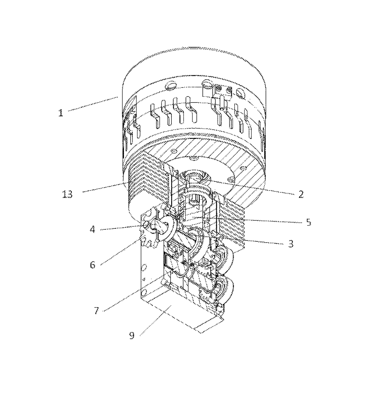
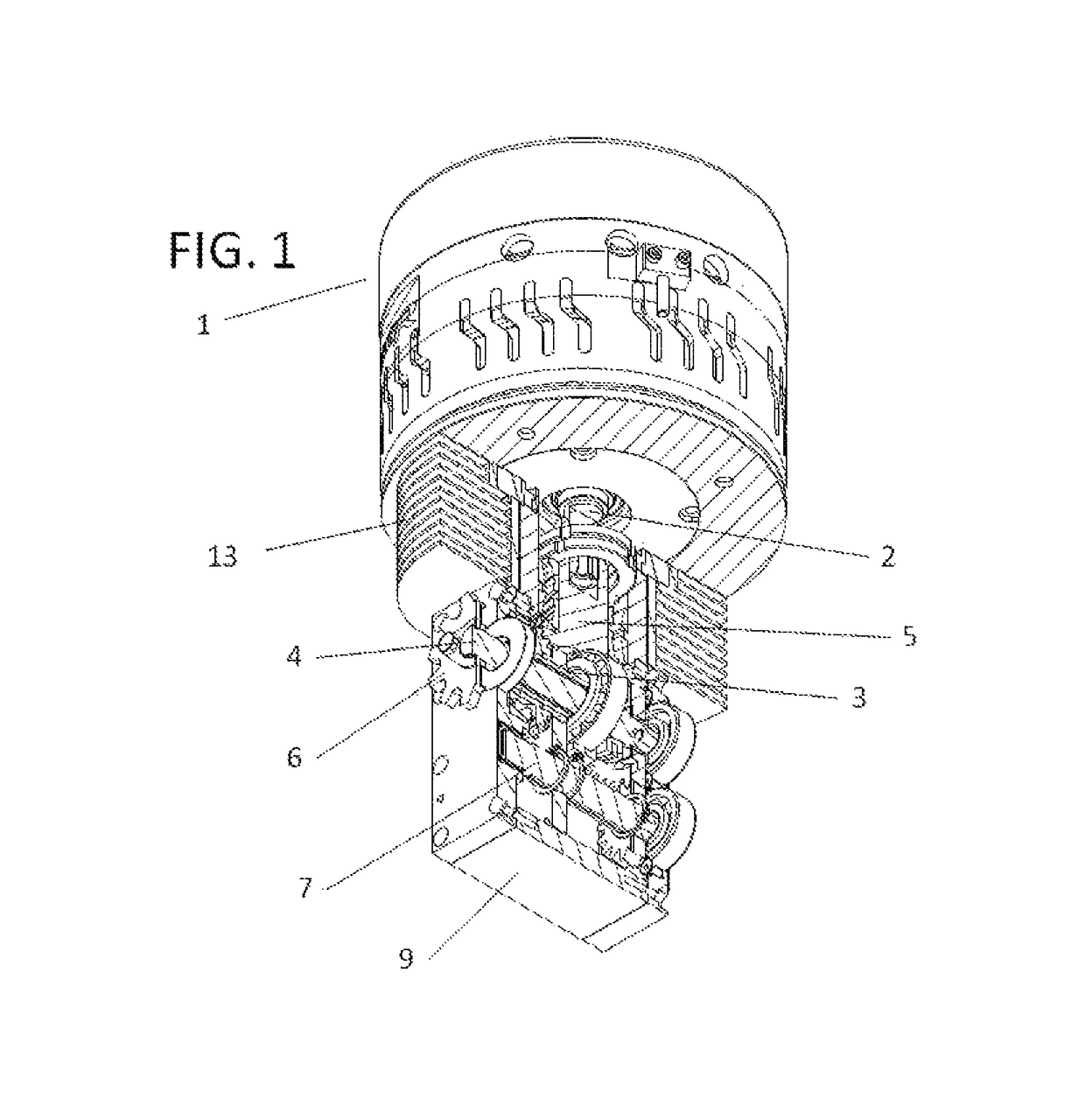
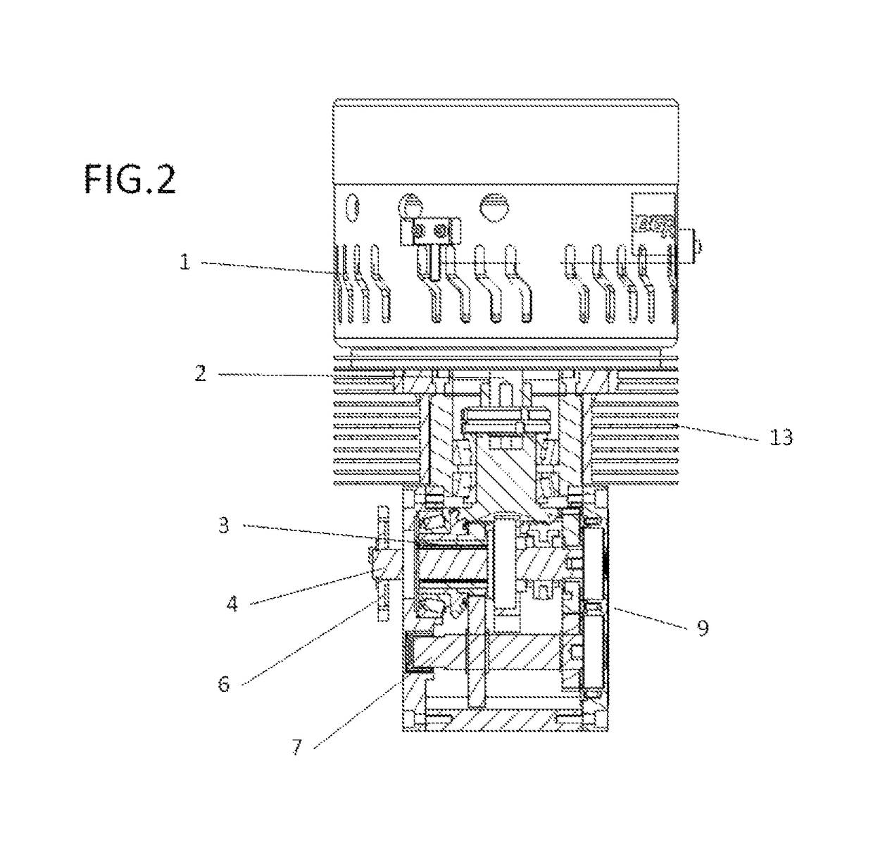
[0016]To solve the aforementioned drawbacks, the vehicle traction device that is the object of the present invention comprises:

[0017]A motor, preferably electric, located symmetrically between the side vertical tubes of a vehicle frame.

[0018]The term “vertical” used in relation to the tubes of a vehicle frame means that the tubes extend from a lower position of the vehicle to an upper position of the vehicle.

[0019]A primary shaft coplanar and concurrent with the rotation shaft of the motor, wherein the two said shafts engage one another in the center zone of an axial extension of the primary shaft, and wherein the primary shaft directly receives the force from the motor.

[0020]An output shaft that transmits the force from the motor to the drive wheel or wheels, through a gearwheel with a chain, belt pulley or cardan shaft.

[0021]The primary shaft is coaxial to the output shaft, wherein the output shaft axially crosses said primary shaft.

[0022]In a simple embodiment, the primary and ou...


PUM


Abstract

Vehicle traction device, mainly for land vehicles, of the type comprising a motor and a transmission wherein the motor preferably has an axial rotation, such as an electric motor, wherein the motor rotation is coplanar and concurrent with the primary shaft of the transmission, and wherein the primary shaft is in turn coaxial to the output shaft, such that the output shaft crosses the primary shaft and extends beyond the ends thereof.

Description

CROSS REFERENCE TO RELATED APPLICATIONS[0001]This application is a National Stage application of PCT / EP2014 / 070584, titled “Vehicle Traction Device and Vehicle Incorporating Same” and filed Sep. 24, 2014, which claims the benefit of Spanish Patent Application No. ES 201331406, titled “Vehicle Traction Device and Vehicle Incorporating Same” and filed Sep. 26, 2013. The contents of PCT / EP2014 / 070584 and ES 201331406 are hereby incorporated herein in their entirety.[0002]As indicated by the title, the subject matter of the present invention relates to a vehicle traction device, for land vehicles mainly, of the type comprising a motor and a transmission, wherein the motor preferably has a coaxial rotation, as in an electric motor, and wherein the rotation shaft of the motor is coplanar and concurrent with the primary shaft of the transmission.[0003]The aforementioned primary shaft is in turn coaxial with the output shaft, such that the output shaft crosses the primary shaft and extends ...

Claims


Application Information

Patent Timeline
Patent Type & Authority Patents(United States)
IPC IPC(8): B60K1/00B62M7/06B62K11/04B60K17/08B60K11/06B60K5/06B60K1/04B62M17/00B60K5/00B60K1/02
CPCB62M17/00B60K1/04B60K5/06B60K11/06B60K17/08B62K11/04B62M7/06B60K1/00B62K2208/00B60K1/02B60K5/00B60K2001/006B60K2001/0422B60Y2200/12B62K2204/00B62J43/20B62J43/28B62M6/55B62M7/02
Inventor BLASCO GRACIA, FRANCISCO JOSEBLASCO GRACIA, ULISES
Owner B Y M INGOS
Why Eureka
Try Eureka