Vehicle Traction Device and Vehicle Incorporating Same

a technology of vehicle traction and traction device, which is applied in the direction of motorcycling, cycles, transportation and packaging, etc., can solve the problems of infrequent use of electric motors in two-wheel vehicles, large and heavy batteries, and complicated transmission, so as to improve the cooling effect of air and enhance the passage of air

Active Publication Date: 2016-08-04
B Y M INGOS
View PDF4 Cites 3 Cited by
  • Summary
  • Abstract
  • Description
  • Claims
  • Application Information

AI Technical Summary

Benefits of technology

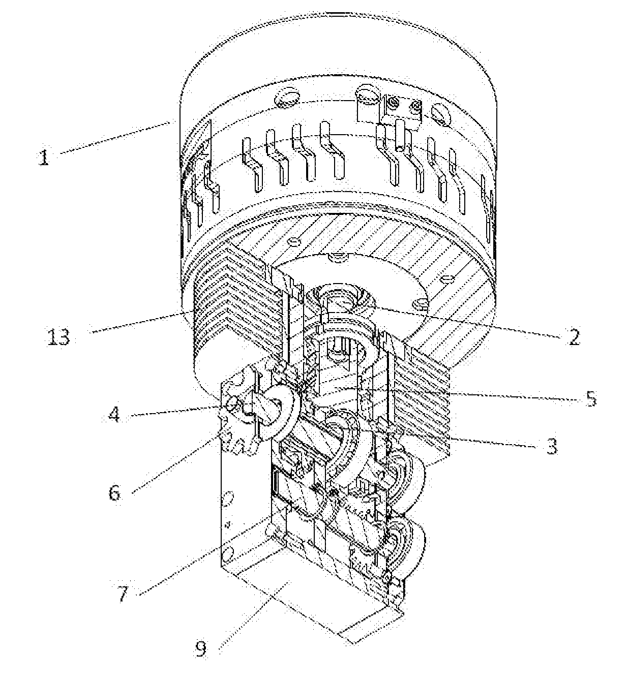
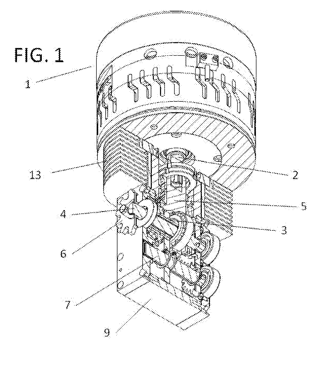
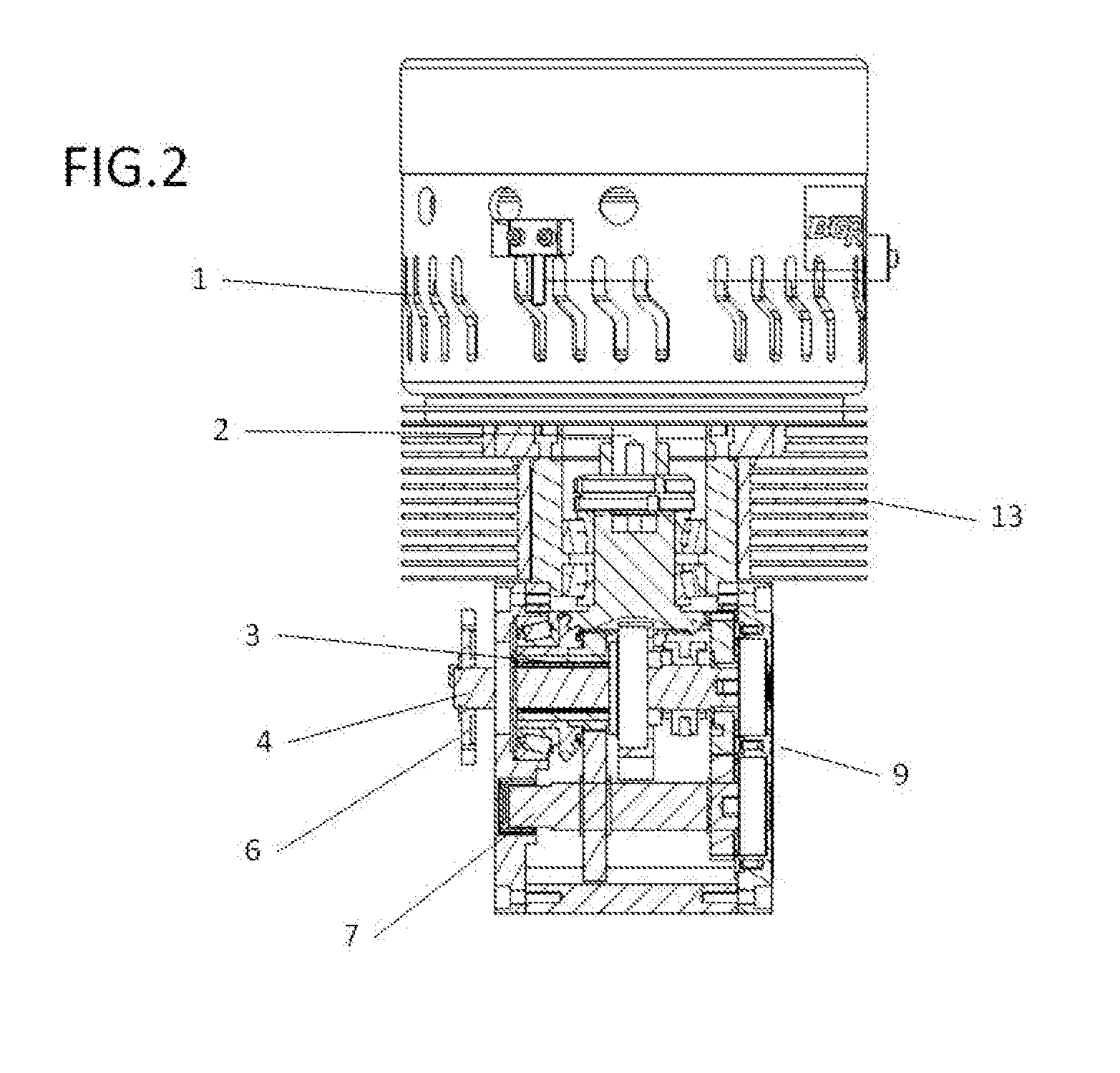
[0040]To optimize the cooling action of the air when the motor is operating, the invention comprises a number of cooling fins

Problems solved by technology

One of the main drawbacks of the use of electric motors is the need for batteries which, in general, are large and heavy.
Currently, however, electric motors are infrequently used in two-wheel vehicles as the weight and location of the batteries, as well as the position of the rotation shaft of the electric motor hinder their use.
Another problem faced by two-wheel vehicles is the swinging of the rear wheel suspension, which complicates the transmission and generates tensions and overloads in the transmission chains.
Therefore, the motor weight distribution is necessarily uneven on the two sides of the

Method used


Image

  • Vehicle Traction Device and Vehicle Incorporating Same
  • Vehicle Traction Device and Vehicle Incorporating Same
  • Vehicle Traction Device and Vehicle Incorporating Same

Examples


Embodiment Construction

[0015]To solve the aforementioned drawbacks, the vehicle traction device that is the object of the present invention comprises:

[0016]A motor, preferably electric, located symmetrically between the side vertical tubes of a vehicle frame.

[0017]The term “vertical” used in relation to the tubes of a vehicle frame means that the tubes extend from a lower position of the vehicle to an upper position of the vehicle.

[0018]A primary shaft coplanar and concurrent with the rotation shaft of the motor, wherein the two said shafts engage one another in the center zone of an axial extension of the primary shaft, and wherein the primary shaft directly receives the force from the motor.

[0019]An output shaft that transmits the force from the motor to the drive wheel or wheels, through a gearwheel with a chain, belt pulley or cardan shaft.

[0020]The primary shaft is coaxial to the output shaft, wherein the output shaft axially crosses said primary shaft.

[0021]In a simple embodiment, the primary and ou...


PUM


Abstract

Vehicle traction device, mainly for land vehicles, of the type comprising a motor and a transmission wherein the motor preferably has an axial rotation, such as an electric motor, wherein the motor rotation is coplanar and concurrent with the primary shaft of the transmission, and wherein the primary shaft is in turn coaxial to the output shaft, such that the output shaft crosses the primary shaft and extends beyond the ends thereof.

Description

[0001]As indicated by the title, the subject matter of the present invention relates to a vehicle traction device, for land vehicles mainly, of the type comprising a motor and a transmission, wherein the motor preferably has a coaxial rotation, as in an electric motor, and wherein the rotation shaft of the motor is coplanar and concurrent with the primary shaft of the transmission.[0002]The aforementioned primary shaft is in turn coaxial with the output shaft, such that the output shaft crosses the primary shaft and extends beyond the ends thereof.[0003]The primary shaft is considered to be that which receives the force from the motor because it is connected to the rotation shaft of the same, and the output shaft is considered to be that which, through the transmission, is connected to the drive wheel or wheels.[0004]The present invention is applicable in the field of vehicles.BACKGROUND OF THE INVENTION[0005]Electric motors are increasingly being used in all types of vehicles, part...

Claims


Application Information

Patent Timeline
IPC IPC(8): B62M17/00B62M7/06B62K11/04B60K5/06B60K1/00B60K11/06
CPCB60K1/00B62M17/00B60K1/04B60K5/00B60K5/06B60K11/06B60K17/08B60K2001/006B60K2001/0422B60Y2200/12B62K2204/00B62K11/04B62K2208/00B62M7/06B60K1/02B62J43/20B62J43/28B62M6/55B62M7/02
Inventor BLASCO GRACIA, FRANCISCO JOSEBLASCO GRACIA, ULISES
Owner B Y M INGOS
Why Eureka
Try Eureka