
Optical fiber ribbon and optical fiber cable housing the optical fiber ribbon

a technology of optical fiber ribbon and optical fiber cable, which is applied in the direction of optics, fibre mechanical structures, instruments, etc., can solve the problems of inability to differentiate ribbons during installation operation, increase transmission loss at the time of mid-span access of live wires, etc., to prevent optical fiber transmission loss and optical fiber separation

Active Publication Date: 2015-02-19
THE FUJIKURA CABLE WORKS LTD +1
View PDF1 Cites 7 Cited by
  • Summary
  • Abstract
  • Description
  • Claims
  • Application Information

AI Technical Summary

Benefits of technology

The present invention provides an optical fiber ribbon that can ensure both mid-span access performance and cable production performance. The split strength of the connecting portions connecting adjacent optical fibers is set in a specific range to prevent transmission loss and unintended breakage during mid-span access and production. This ensures the optical fibers are always connected and reduces the likelihood of separation.

Problems solved by technology

For example, if the strength of the connecting portions is excessively high, transmission loss at the time of mid-span access of live wires increases because of tensile force caused when the connecting portions are separated.
On the other hand, if the strength of the connection portions is too low, the connecting portions are broken up and the optical fibers are thus separated if the optical fiber ribbon is locally bent at the time of cable production, installation, and the like so that ribbon differentiation during the operation of installation may not be possible.

Method used


Image

  • Optical fiber ribbon and optical fiber cable housing the optical fiber ribbon
  • Optical fiber ribbon and optical fiber cable housing the optical fiber ribbon
  • Optical fiber ribbon and optical fiber cable housing the optical fiber ribbon

Examples


example

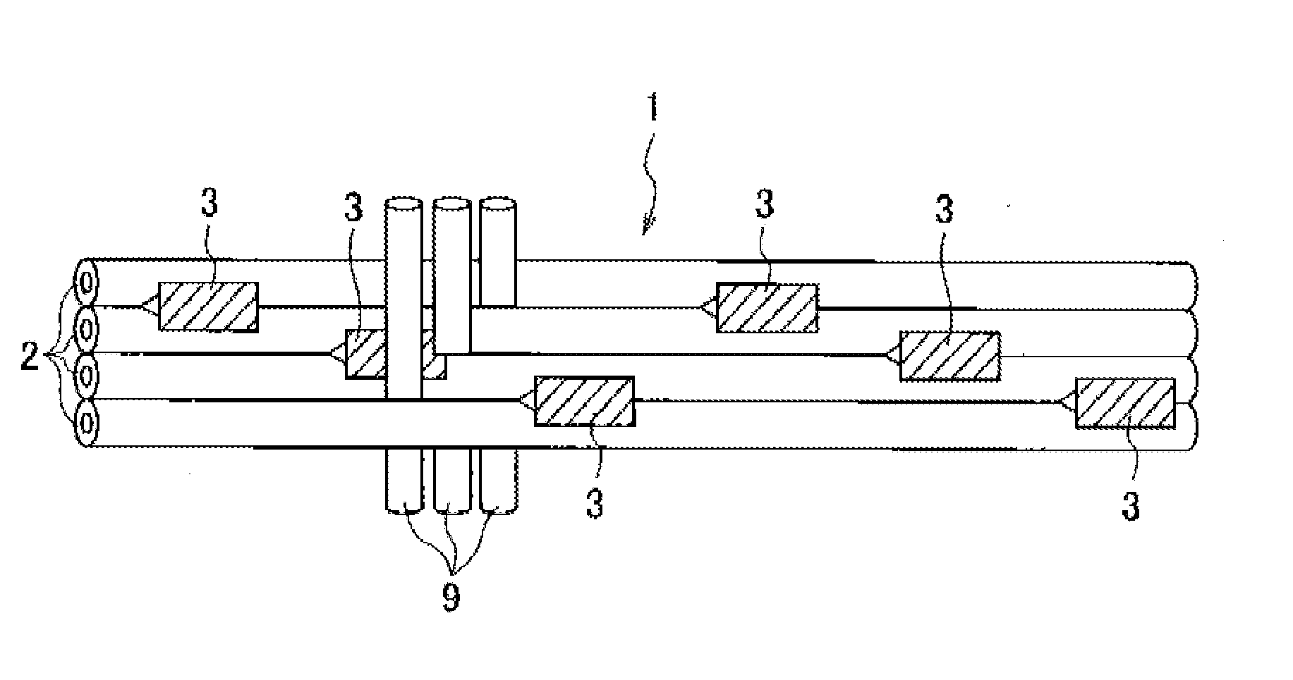
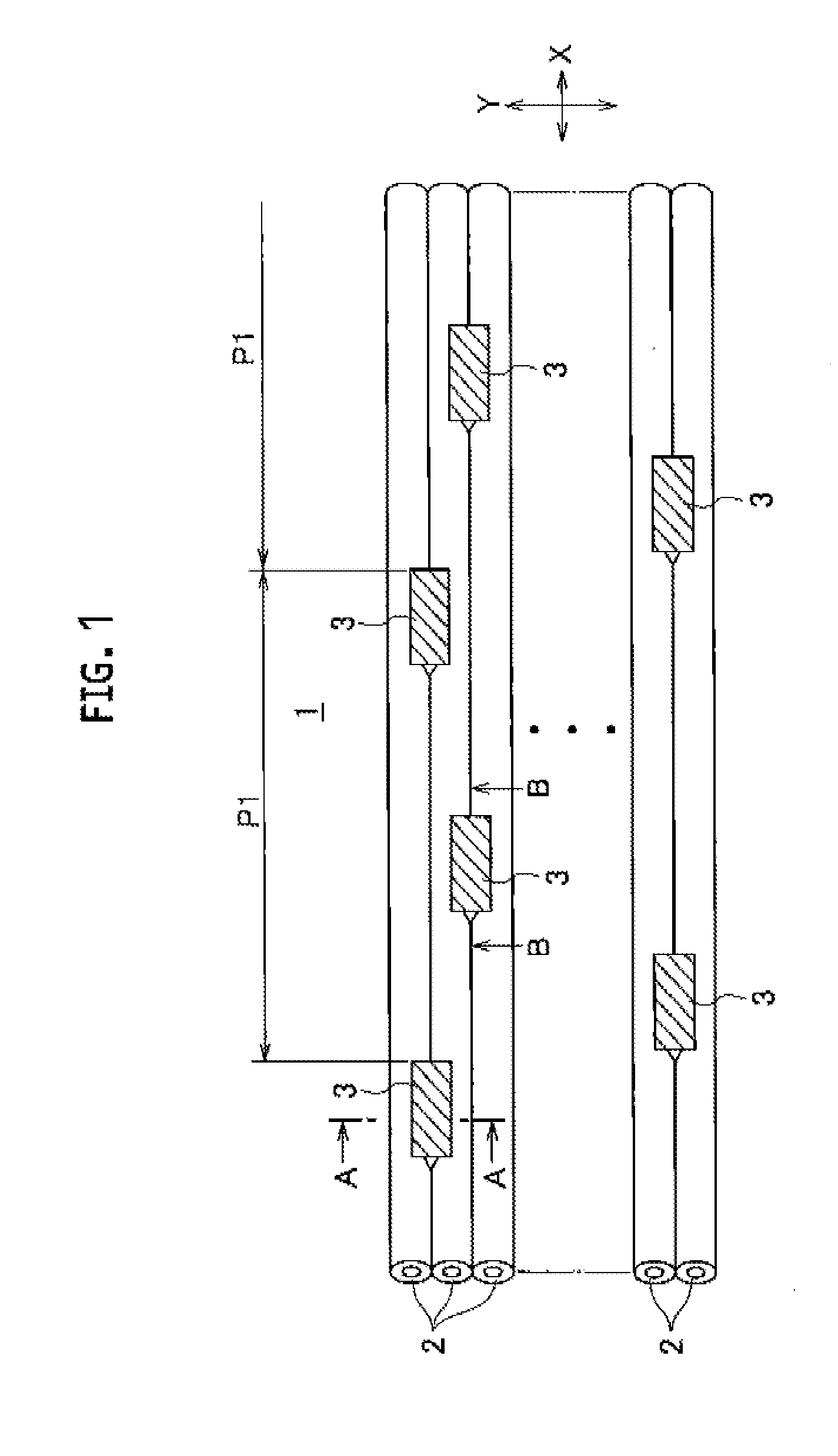
[0028]In the example, a 4-core optical fiber ribbon having an intermittently-fixed structure was manufactured, as shown in FIG. 1, in a manner such that four colored optical fibers each having a diameter of 250 μm were arranged in parallel and connected with connecting portions which were intermittently formed in each of a ribbon longitudinal direction and a ribbon width direction. The optical fibers used in the example were optical fibers conforming to ITU-T G.652B of the IEC standard.

[0029]The optical fiber ribbon thus manufactured was subjected to a connecting portion split test and a mid-span access test in accordance with the following methods. As shown in FIG. 3, the connecting portion split test was carried out, for example, in a manner such that one of the four optical fibers 2 was fixe to a fixing jig 8, and another optical fiber 2 connected via the connecting portion 3 to the optical fiber 2 fixed to the fixing jig 8 was pulled in the direction away from the fixing jig 8, ...


PUM


Abstract

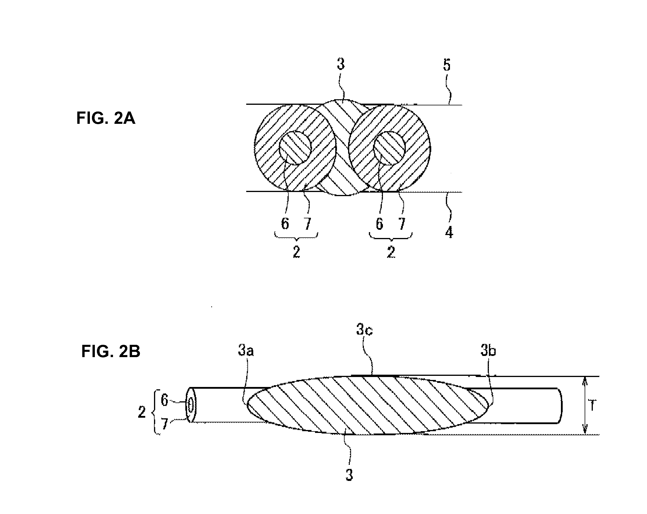
Provided is an optical fiber ribbon capable of concurrently ensuring mid-span access performance and cable production performance. The optical fiber ribbon 1 includes three or more optical fibers 2 arranged in parallel and connecting portions 3 connecting the adjacent optical fibers 2, the connecting portions 3 being formed intermittently in each of a ribbon longitudinal direction X and a ribbon width direction Y. The optical fiber ribbon 1 including the connecting portions 3 having split strength which is set in the range from 1.50 gf to 21.0 gf, contributes to exhibiting both the mid-span access performance and the cable production performance.

Description

CROSS-REFERENCE TO RELATED APPLICATION[0001]The application is a Continuation of PCT Application No. PCT / JP2013 / 055138, filed on Feb. 27, 2013, and claims the benefit of priority from the prior Japanese Patent Application No. 2012-046443, filed on Mar. 2, 2012, the entire contents of which are incorporated herein by reference.BACKGROUND OF THE INVENTION[0002]The present invention relates to an optical fiber ribbon having an intermittently-fixed structure in which optical fibers adjacent to each other are intermittently connected with connecting portions, and also relates to an optical fiber cable housing the optical fiber ribbon.BACKGROUND ART[0003]There has been an increased demand for higher density and reduction in diameter in the technical field of optical fiber cables. For example, Patent Literature 1 teaches an example of measures to achieve higher density and reduction in diameter in an optical fiber cable.[0004]An optical fiber ribbon described in Japanese Patent No. 4143651...

Claims


Application Information

Patent Timeline
Patent Type & Authority Applications(United States)
IPC IPC(8): G02B6/44
CPCG02B6/4403G02B6/4431
Inventor ISAJI, MIZUKISAJIMA, YOSHIEOSATO, KENOKADA, NAOKIMATSUZAWA, TAKASHITAKE, YUKIKOYAMADA, YUSUKEHAMAGUCHI, SHINYAKAKUTA, DAISUKENAKANE, HISAAKI
Owner THE FUJIKURA CABLE WORKS LTD
Learn More