Fuel cell stack and seal plate used for the same

Active Publication Date: 2015-02-19
NISSAN MOTOR CO LTD
View PDF23 Cites 10 Cited by
  • Summary
  • Abstract
  • Description
  • Claims
  • Application Information

AI Technical Summary

Benefits of technology

[0007]Accordingly, the present invention has an objective of providing a fuel cell stack and a seal plate used in the fuel cell stack, which allows continued use of a cell module formed by stacking multiple fuel cells.

Problems solved by technology

This is inefficient.

Method used


Image

  • Fuel cell stack and seal plate used for the same
  • Fuel cell stack and seal plate used for the same
  • Fuel cell stack and seal plate used for the same

Examples


first embodiment

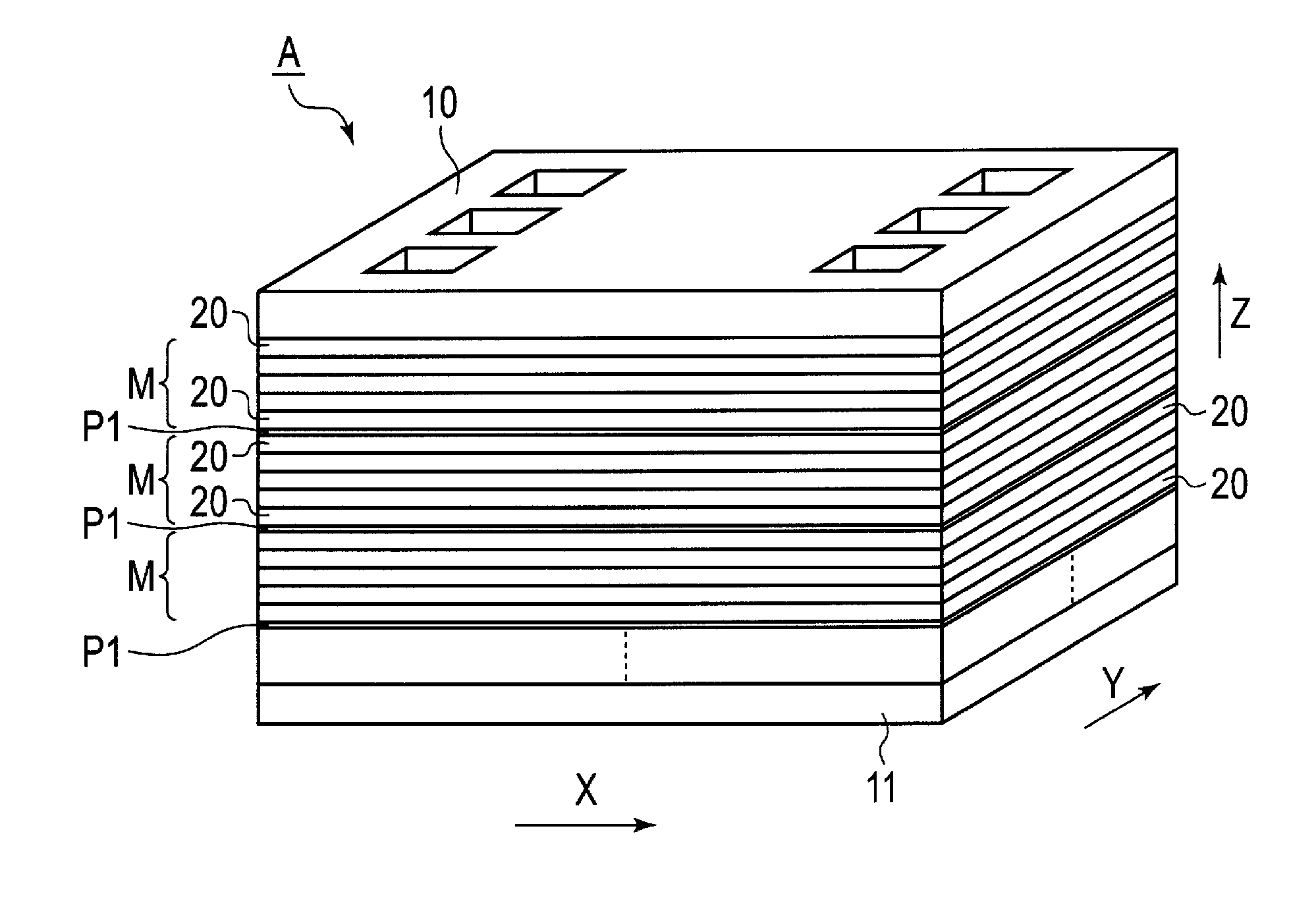
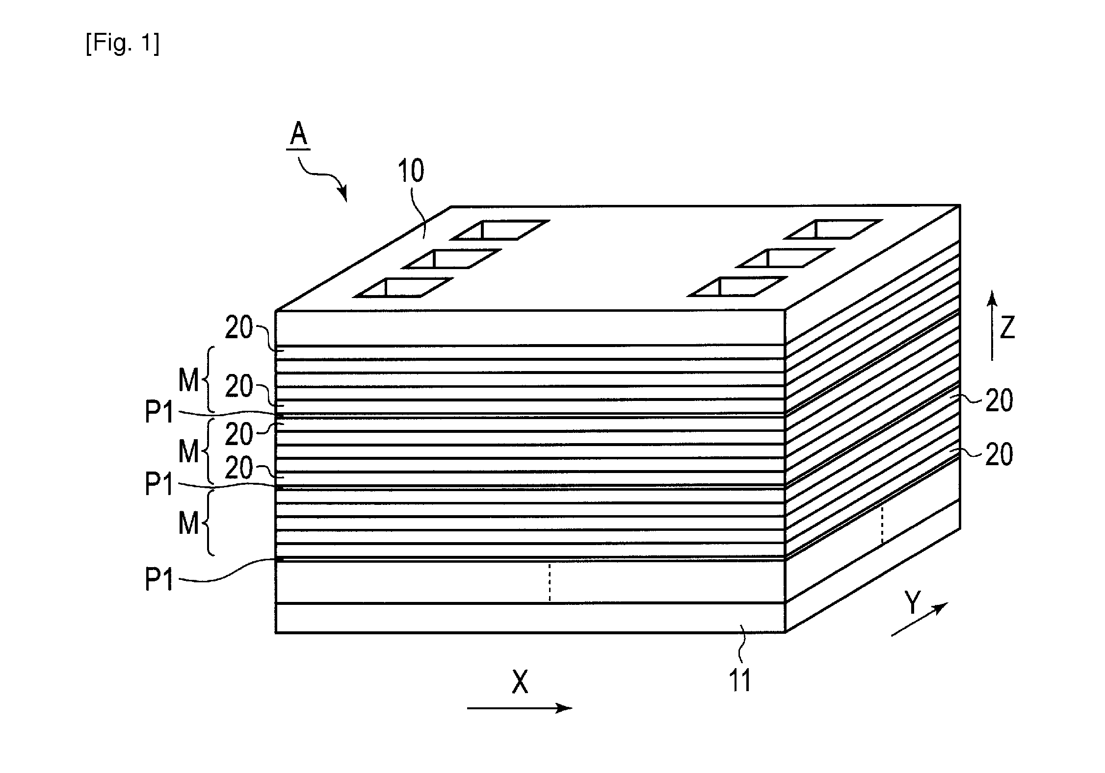
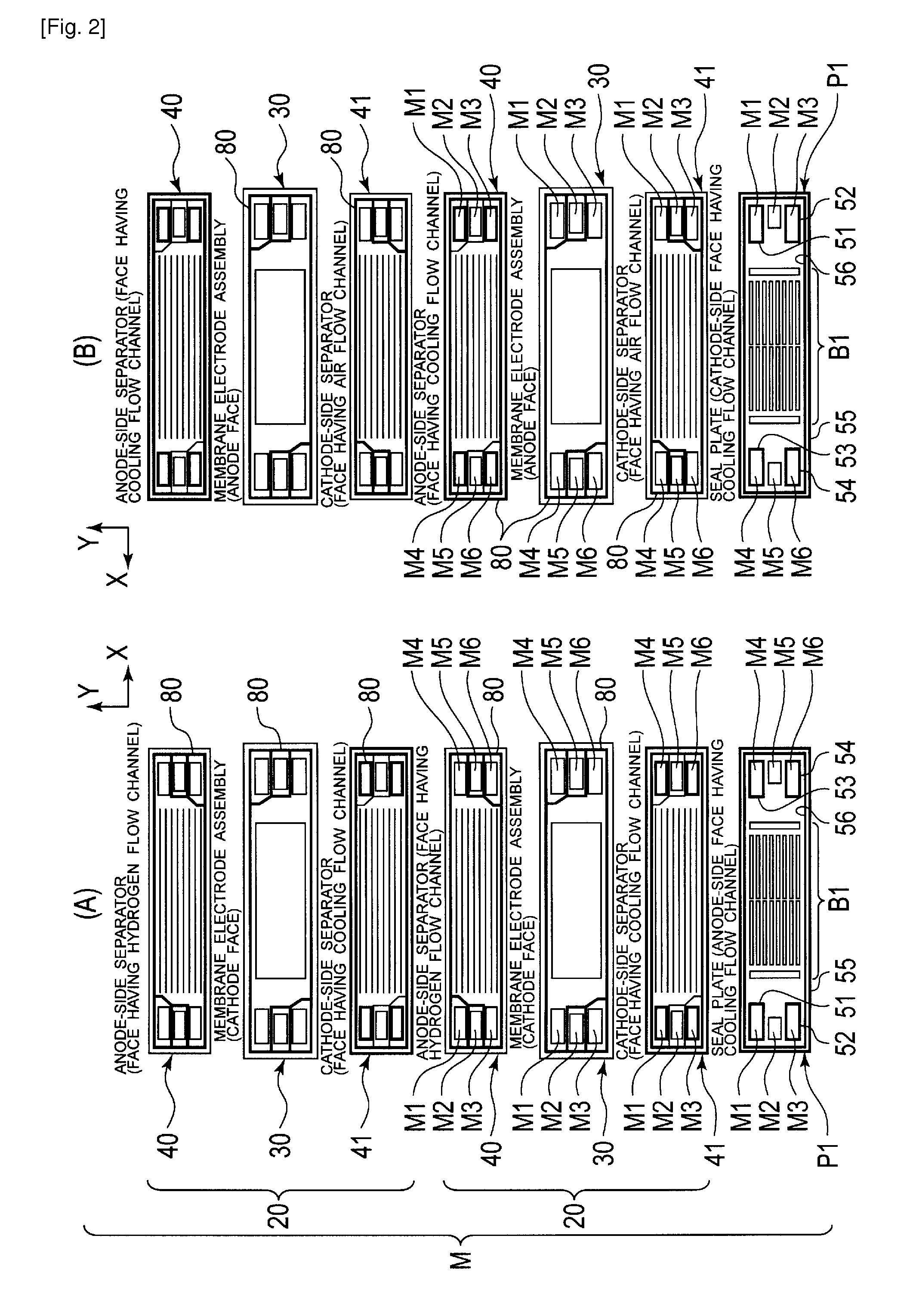
[0035]With reference to the drawings, embodiments of the present invention are described below. FIG. 1 is a perspective external view schematically showing a fuel cell stack according to a first embodiment of the present invention. FIG. 2(A) is plan views each showing one of the faces of a separator, a membrane electrode assembly, or a seal plate constituting a cell module to illustrate their arrangement, and FIG. 2(B) shows plan views each showing the other face thereof. FIG. 3(A) is an enlarged plan view of the membrane electrode assembly, and FIG. 3(B) is an enlarged plan view of the cathode-side separator. FIG. 4 is an enlarged plan view of the seal plate. FIG. 5 is an enlarged sectional view, taken along line C-C in FIG. 4, of part of the fuel cell stack in FIG. 1.

[0036]A fuel cell stack A, according to one example, shown in FIG. 1 has multiple cell modules M stacked on one another. A seal plate P1 is interposed between adjacent ones of the cell modules M. These cell modules M ...

second embodiment

[0094]As shown in FIG. 10, a seal plate P2 according to the second embodiment includes a pressure-drop adjustment portion B2 according to a second example. The pressure-drop adjustment portion B2 has: an upstream array 60A of slits and a downstream array 61A of slits being formed in parallel with the long-axis center line O1 of the plate substrate 50; and two slits 62 extending in parallel with the short-axis center line O2 of the plate substrate 50, which is perpendicular to the long-axis center line O1.

[0095]The upstream array 60A consists of ten slits 60b arranged upstream of the flow direction of the cooling fluid (the X direction). In this embodiment, five slits 60b are arranged on each side of the long-axis center line O1 with a predetermined distance W1 therebetween. Each slit 60b is narrower than the slit 60a described above. The slits 60b have the same length and width and arranged in parallel with each other.

[0096]The downstream array 61A consists of ten slits 61b arranged...

third embodiment

[0098]As shown in FIG. 11, a seal plate P3 according to the third embodiment has a pressure-drop adjustment portion B3 according to a third example. The pressure-drop adjustment portion B3 has: an upstream array 60B of slits and a downstream array 61B of slits being formed in parallel with the long-axis center line O1 of the plate substrate 50; and two slits 62 extending in parallel with the short-axis center line O2 of the plate substrate 50, which is perpendicular to the long-axis center line O1.

[0099]The upstream array 60B consists of fifteen slits 60c arranged upstream of the flow direction of the cooling fluid (the X direction). The slits 60c are arranged in parallel with each other at equal intervals in their short-side direction. The downstream array 61B consists of eight slits 61c arranged downstream of the flow direction of the cooling fluid (the X direction). The slits 61c have the same shape and size as the slits 60c, and are arranged at intervals twice those of the slits...


PUM

PropertyMeasurementUnit
electrical insulation propertyaaaaaaaaaa
thicknessaaaaaaaaaa
thicknessesaaaaaaaaaa

Abstract

A fuel cell stack includes a plurality of cell modules each formed by stacking a plurality of fuel cells, each of the plurality of fuel cells having a membrane electrode assembly having an insulating member at an outer periphery portion thereof and paired separators sandwiching the membrane electrode assembly, and by attaching the insulating members of adjacent fuel cells together, and a seal plate interposed between the stacked cell modules. The seal plate includes a plurality of manifold holes from which two power-generation gases flow separately through the plurality of fuel cells, and a first seal member provided along a peripheral portion of each of the plurality of manifold holes to seal a corresponding one of the two power-generation gases flowing through the manifold hole.

Description

CROSS-REFERENCE TO RELATED APPLICATIONS[0001]This application is a National Stage application of International Patent Application No. PCT / JP2013 / 001444, filed on Mar. 7, 2013, which claims priority to Japanese Patent Application No. 2012-053310, filed on Mar. 9, 2012, and Japanese Patent Application No. 2012-275479, filed Dec. 18, 2012. Japanese Patent Application Nos. 2012-053310 and 2012-275479 as well as International Patent Application No. PCT / JP2013 / 001444 are hereby incorporated by reference in their entirety.TECHNICAL FIELD[0002]The present invention relates to a fuel cell stack formed by stacking multiple fuel cells and to a seal plate used in this fuel cell stack.BACKGROUND ART[0003]An art related to the fuel cell stack according to the present invention is disclosed in “FUEL CELL STACK STRUCTURE” of PTL 1.[0004]In the fuel cell stack structure of PTL 1, multiple cell modules each formed by stacking multiple fuel cells are arranged in a row in a cell-stacking direction, and...

Claims


Application Information

Patent Timeline
Patent Type & Authority Applications(United States)
IPC IPC(8): H01M8/24
CPCH01M8/2485H01M8/2415H01M2250/10H01M8/242H01M8/249H01M8/0271H01M8/0276H01M8/0297H01M2008/1095Y02E60/50H01M8/2483Y02B90/10
Inventor NUMAO, YASUHIROKAGEYAMA, KAZUHIRO
Owner NISSAN MOTOR CO LTD
Why Eureka
Try Eureka