
Securing element for preventing the release of a plug connection between a cable harness plug and a coupler plug

a technology of securing elements and plug connections, which is applied in the direction of securing/insulating coupling contact members, coupling device connections, electrical devices, etc., can solve the problems that the entire plug connection, once it is established, cannot be released easily, and achieve the effect of easy release and simple assembly

Inactive Publication Date: 2007-11-27
ROBERT BOSCH GMBH
View PDF6 Cites 10 Cited by
  • Summary
  • Abstract
  • Description
  • Claims
  • Application Information

AI Technical Summary

Benefits of technology

[0006]One advantage of the present invention is that an additional securing element for protecting a plug-in connection against an unintended release has been created in a very simple manner. The securing element advantageously has a ring-shaped form that is able to be clipped onto the cable harness plug.
[0007]The preferred embodiment has two hinges, parts or segments of the ring-shaped form being able to be rotated about the hinge axis. This makes it very easy to plug it into the one end of the cable harness plug. To mount the securing element on the cable harness, the outwardly pointing sections are brought together and the individual free ends of the segments have a locking element, preferably catching elements, which then tightly press the entire securing element against the periphery of the coupler plug.
[0008]In addition, the securing element has a mushroom-type form which is located on the outer periphery of the ring-shaped securing element. This design extends exclusively across a segment portion of the ring-shaped form. The ring-shaped form brings about with a locking element that is likewise situated on the cable harness. This locking element is provided to safeguard the established plug connection to the coupler plug. As a rule, this plug connection may be released very easily by downward pressure on the locking element. However, due to this mushroom-type design, it is impossible to press the locking element down, so that—once the plug connection has been established—it may be released exclusively by removing the ring-shaped securing element and subsequently actuating the locking element on the cable harness. Since the securing element itself has a locking mechanism, there is no need to destroy the securing element for removal purposes, and the securing element may continue to be used.
[0009]Another advantage of the securing element is that it also has so-called grooved-tube holder on its outer wall. This grooved tube is used to protect the lines leading to the cable harness in an appropriate manner.
[0010]The grooved-tube holder has bulges on its periphery, so that the grooved tube may be retained accordingly by way of a press and / or form connection.
[0011]The grooved-tube holder and securing element are preferably designed as one piece. Due to the one-piece construction the securing element may already be positioned in a grooved tube, so that a very simple assembly together with the grooved tube and the securing element is possible on a cable harness.

Problems solved by technology

Secondly, securing elements that ensure that an entire plug connection, once it has been established, cannot be released easily, are also known from the related art.

Method used


Image

  • Securing element for preventing the release of a plug connection between a cable harness plug and a coupler plug
  • Securing element for preventing the release of a plug connection between a cable harness plug and a coupler plug
  • Securing element for preventing the release of a plug connection between a cable harness plug and a coupler plug

Examples


Embodiment Construction

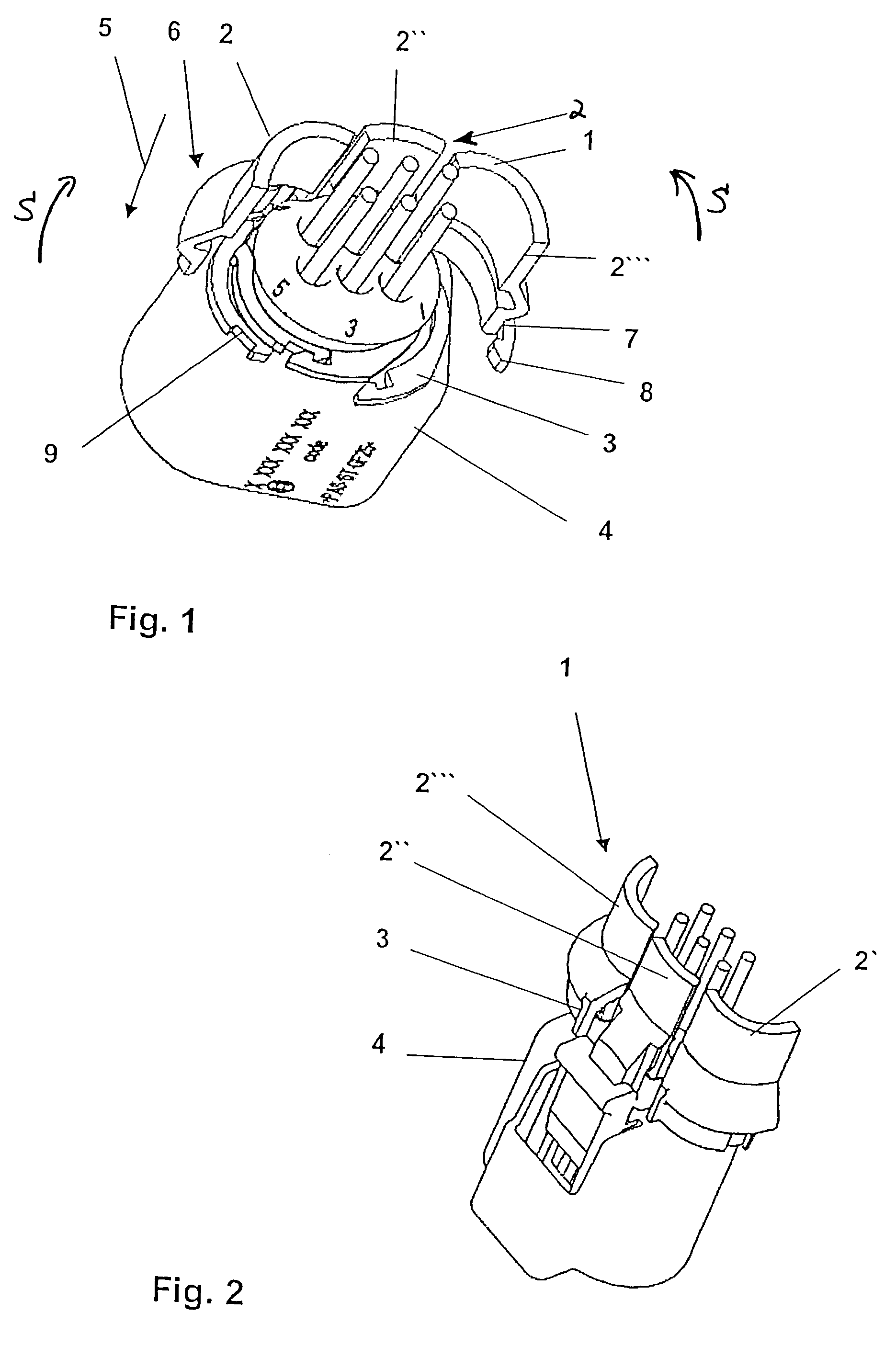
[0017]FIGS. 1 and 2 show a perspective view of a securing element 1 according to the present invention in a position prior to installation. Securing element 1 includes a ring-shaped body 2 having three segments, 2′, 2″ and 2′″, center segment 2″ being mounted directly on base element 3 of cable harness plug 4 shown here in a manner not shown in greater detail in FIGS. 1 and 2.

[0018]To reach the final position shown in FIG. 1, segment parts 2′ and 2′″ pivot in the direction of pivoting arrows S according to FIG. 1 until reaching the position illustrated here. In addition, ends 6 of segments 2′ and 2′″ have a locking element 7. Here, in the exemplary embodiment shown in FIG. 1, this locking element is made up of a detent 8 which engages with a recess 9 in the locked state of securing element 1.

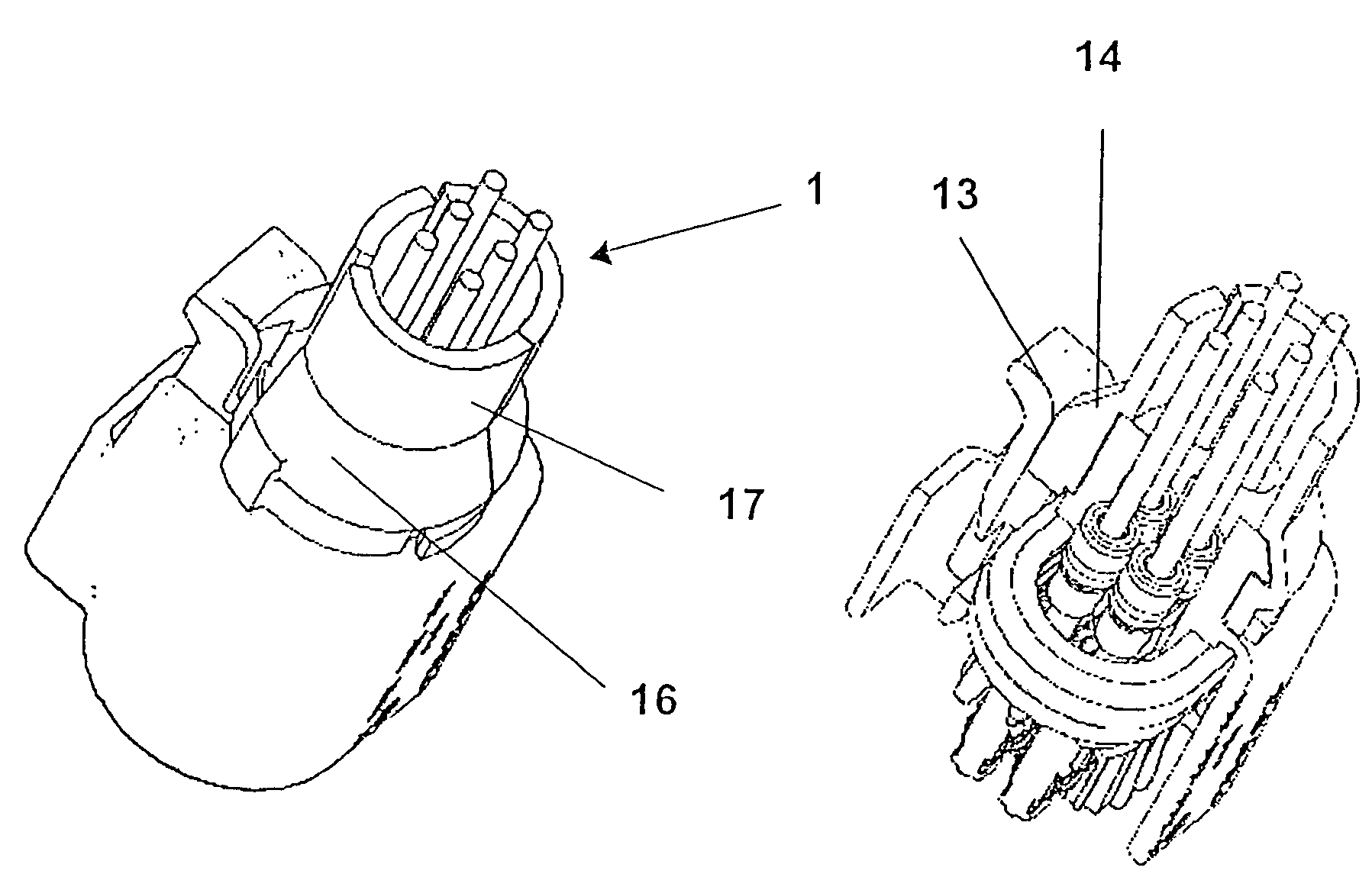
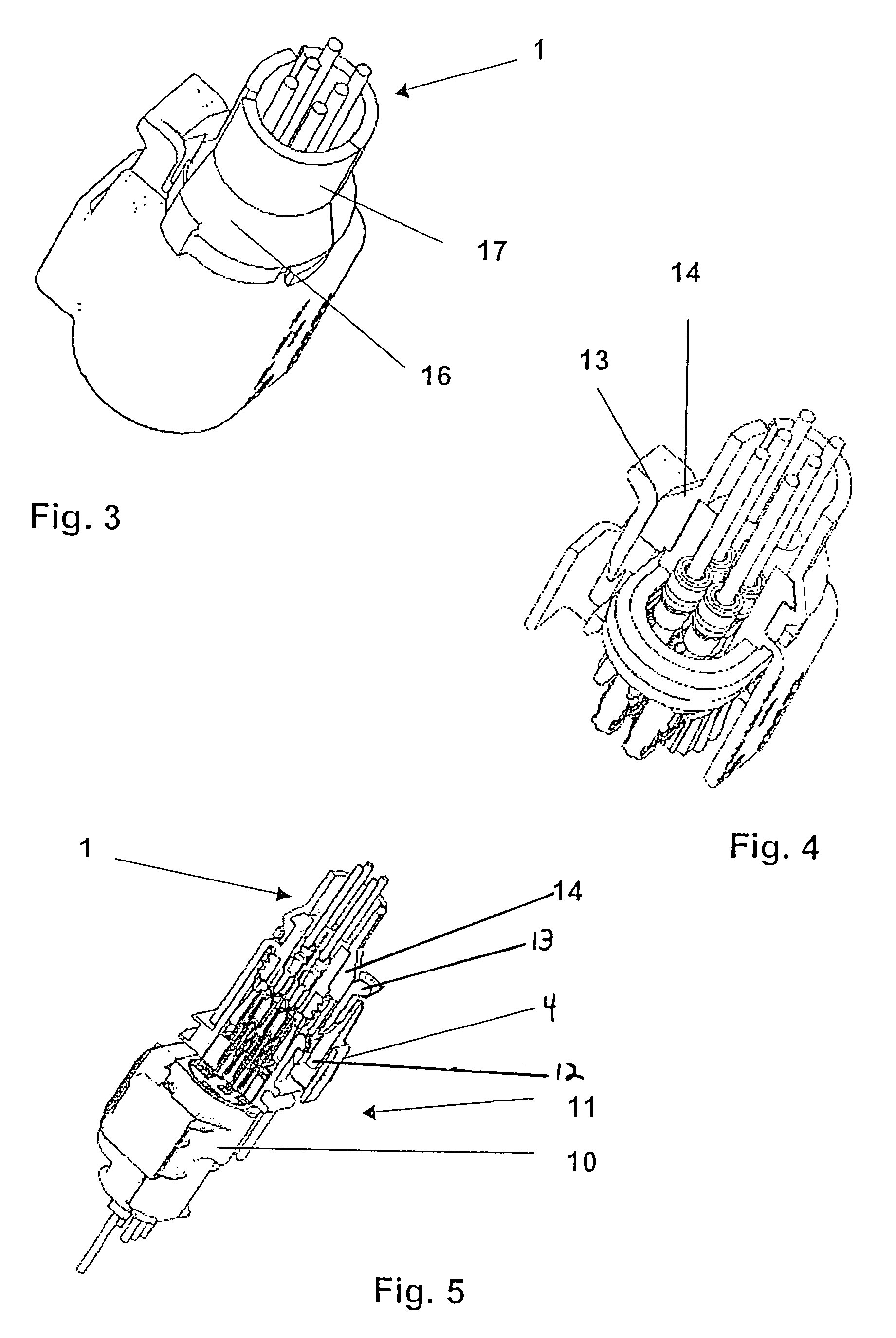
[0019]FIGS. 3 through 5 show securing element 1 illustrated in FIGS. 1 and 2 in the latched position.

[0020]In particular in FIG. 5, both cable harness plug 4 and a coupler plug 10 are provided, ...


PUM


Abstract

A securing element for protecting against an unintentional release of a plug connection between a cable harness plug and a coupler plug. The securing element is distinguished in that it may easily be mounted on the side of a cable harness plug facing away in the plug-in direction, and, once the securing element has assumed the final position, it additionally causes a region of the locking element provided on the cable harness plug to be blocked. In an advantageous further development, securing element also has a grooved-tube retainer which is integrally joined to the securing element.

Description

FIELD OF THE INVENTION[0001]The present invention relates to a securing element for preventing an unintentional release of a plug connection between a cable harness plug and a coupler plug.BACKGROUND INFORMATION[0002]Especially plug connections with a low number of pins, but also coupler plugs in the form of a lambda probe must be coupled via a coupler plug. To ensure that, first of all, the plug connection is implemented correctly, a variety of securing elements are already known. Secondly, securing elements that ensure that an entire plug connection, once it has been established, cannot be released easily, are also known from the related art. The latter may be subdivided into safety mechanisms that must first be destroyed to reverse the plug connection and those in which the securing element must actively be removed so as to likewise release a plug connection.SUMMARY OF THE INVENTION[0003]It is an objective of the present invention to produce a securing element that is releasable ...

Claims


Application Information

Patent Timeline
Patent Type & Authority Patents(United States)
IPC IPC(8): H01R13/502H01R13/639
CPCH01R13/639
Inventor DEJA, LEOKADIAPADE, WOLFGANG
Owner ROBERT BOSCH GMBH
Learn More