Method and apparatus for inspecting workpieces

a technology for workpieces and measuring devices, applied in measurement devices, instruments, special data processing applications, etc., can solve problems such as dynamic errors and inapplicability

Inactive Publication Date: 2015-02-19
RENISHAW PLC
View PDF4 Cites 15 Cited by
  • Summary
  • Abstract
  • Description
  • Claims
  • Application Information

AI Technical Summary

Benefits of technology

[0021]correcting the measurements of the one or more second workpieces using said error map or lookup table or error function.

Problems solved by technology

However, if high accuracy is required, this technique would require the use of a very large number of balls, say 10,000, which is not practical.
Dynamic errors occur as a result of bending of various parts of the apparatus or the probe during accelerating movements.

Method used


Image

  • Method and apparatus for inspecting workpieces
  • Method and apparatus for inspecting workpieces
  • Method and apparatus for inspecting workpieces

Examples


Embodiment Construction

[0057]Measurement Apparatus

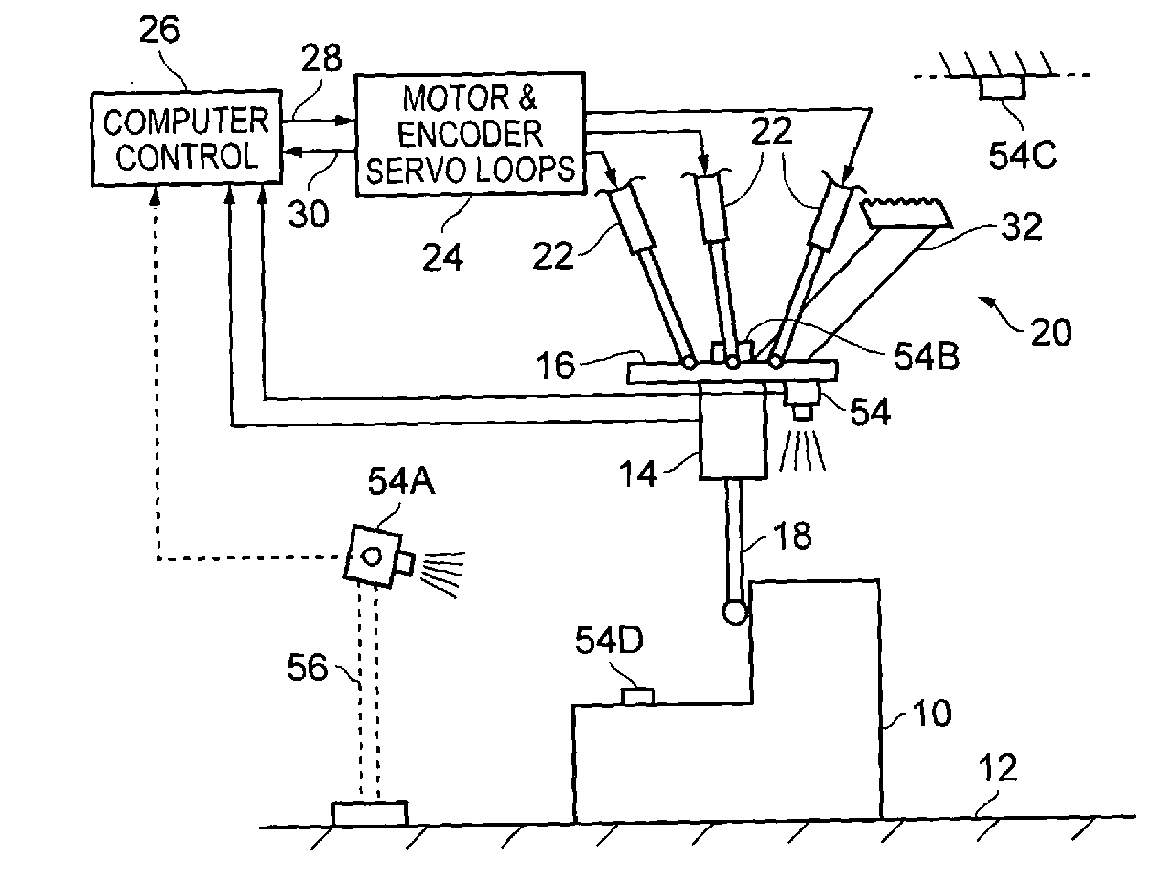
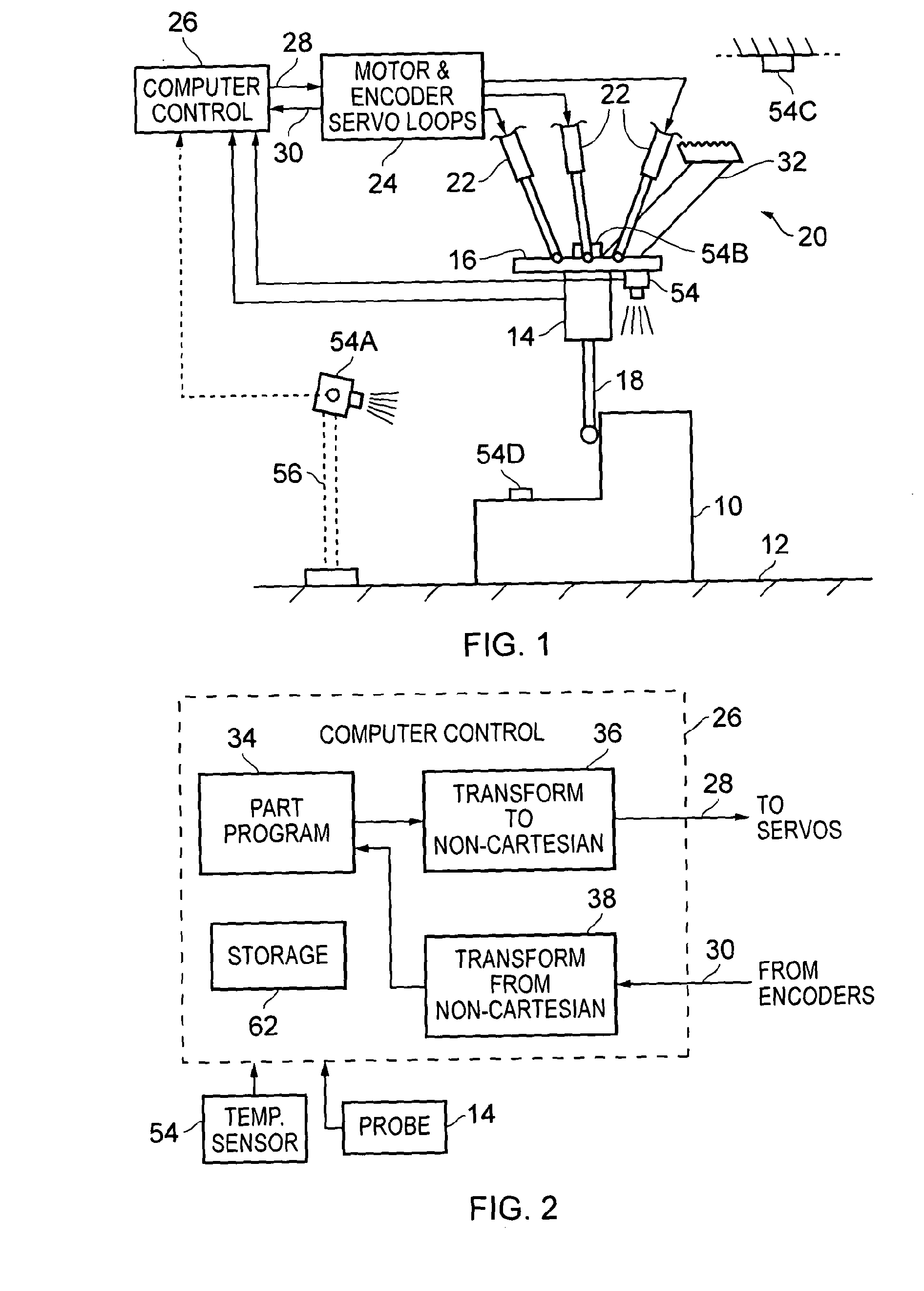
[0058]In the coordinate measuring machine shown in FIG. 1, a workpiece 10 which is to be measured is placed on a table 12 (which forms part of the fixed structure of the machine). A probe having a body 14 is mounted to a movable platform member 16. The probe has a displaceable elongate stylus 18, which in use is brought into contact with the workpiece 10 in order to make dimensional measurements.

[0059]The movable platform member 16 is mounted to the fixed structure of the machine by a supporting mechanism 20, only part of which is shown. In the present example, the supporting mechanism 20 is as described in International Patent Applications WO 03 / 006837 and WO 2004 / 063579. It comprises three telescopic extensible struts 22, extending in parallel between the platform 16 and the fixed structure of the machine. Each end of each strut 22 is universally pivotably connected to the platform 16 or to the fixed structure respectively, and is extended and retracted ...


PUM


Abstract

Methods are described for measuring series of nominally identical production workpieces on a dimensional measuring apparatus such as a coordinate measuring machine. One master workpiece of the series is calibrated, to provide correction values which are used to build an error map of the measuring apparatus. This map is used to correct measurements not only of subsequent nominally identical workpieces of the same series, but also of multiple different subsequent series of different workpieces. Each subsequent series also has a master workpiece which is calibrated and used to further build the error map. As this process is repeated over time, the error map becomes more and more densely populated. In due course, it becomes possible to dispense with the use of a calibrated master workpiece, because measurements can be corrected using error values which already exist in the error map.

Description

FIELD OF THE INVENTION[0001]This invention relates to coordinate measuring apparatus for inspecting the dimensions of workpieces. Coordinate measuring apparatus include, for example, coordinate measuring machines (CMM), machine tools, manual coordinate measuring arms and inspection robots.DESCRIPTION OF PRIOR ART[0002]After workpieces have been produced, it is known to inspect them on a coordinate measuring machine (CMM) having a movable member supporting a probe, which can be driven within a three-dimensional working volume of the machine.[0003]The CMM (or other coordinate measuring apparatus) may be a so-called Cartesian machine, in which the movable member supporting the probe is mounted via three serially-connected carriages which are respectively movable in three orthogonal directions X,Y,Z. Alternatively, it may be a non-Cartesian machine, for example comprising three or six extensible struts which are each connected in parallel between the movable member and a relatively fixe...

Claims


Application Information

Patent Timeline
Patent Type & Authority Applications(United States)
IPC IPC(8): G01B21/04
CPCG01B21/045
Inventor JONAS, KEVYN BARRY
Owner RENISHAW PLC
Why Eureka
Try Eureka