
Airbag device

Active Publication Date: 2015-02-26
AUTOLIV DEV AB
View PDF7 Cites 0 Cited by
  • Summary
  • Abstract
  • Description
  • Claims
  • Application Information

AI Technical Summary

Benefits of technology

The present invention provides an airbag device that is simple and inexpensive, and prevents multiple protective covers from rotating and twisting in relation to the airbag. This simplifies the manufacturing process and reduces manufacturing costs.

Problems solved by technology

As a result, since the entire protective cover is long, it is not desirable to form the protective cover as an integral body when transportation or the like before attachment to a vehicle is taken into consideration.
If protective covers are attached to a vehicle in a state where the airbag is twisted, the airbag may not be deployed properly between an occupant and a side window or the like in the event of a crash and may be unable to protect the occupant.
Besides this, a dangerous situation may occur.
However, since it is necessary to form a complex male or female engagement portion in the end of each protective cover and to engage the engagement portions, the steps for manufacturing the protective covers become complex.
Moreover, although a connecting mechanism may be manufactured as a separate component and be attached to the end of the protective cover, the number of components may increase, which may increase the manufacturing cost.
Moreover, when trying to rotate the protective cover excessively against the suppression, since the direction of the tab will not be approximately in parallel with the longitudinal direction of the airbag, it is possible to easily perceive from the outside that the airbag is twisted therein.
As a result, it is impossible to rotate only one of the first and second protective covers about the longitudinal direction of the airbag.

Method used


Image

  • Airbag device
  • Airbag device
  • Airbag device

Examples


Embodiment Construction

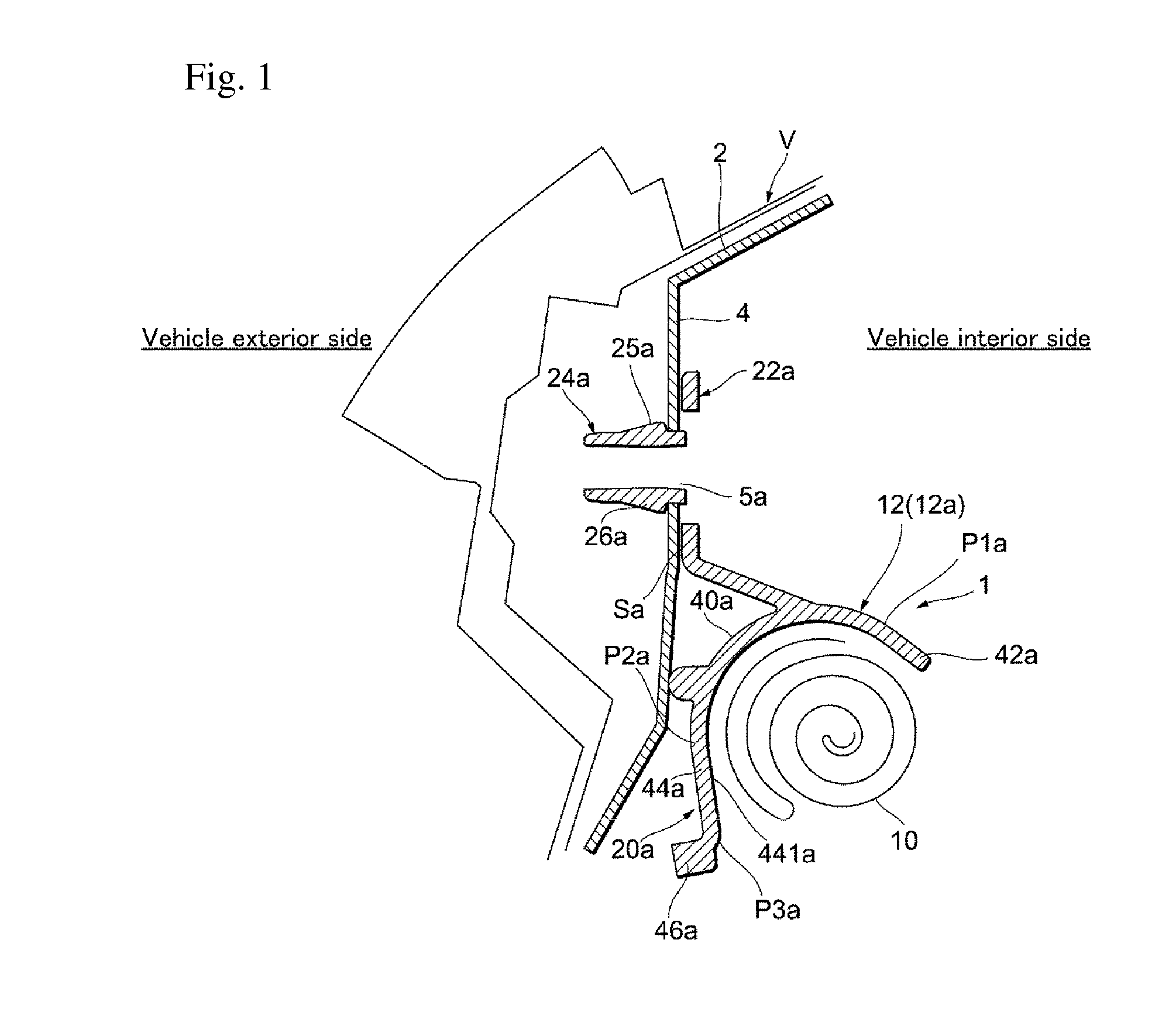
[0035]Hereinafter, an embodiment of the present invention will be described with reference to accompanying drawings. For better understanding of the description, the same constituent components in the respective drawings will be denoted by the same reference numerals as much as possible, and redundant description thereof will not be provided.

[0036]An airbag device according to an embodiment of the present invention will be described with reference to FIG. 1. FIG. 1 is a cross-sectional view illustrating a state where an airbag device 1 according to an embodiment of the present invention is attached to a vehicle V. FIG. 1 illustrates a cross-section when the airbag device 1 in a state of being attached to a roof side rail 2 of the vehicle V is cut along a plane vertical to a front-rear direction of the vehicle V. The roof side rail 2 is configured to form a closed cross-section by welding a plurality of panel members and the airbag device 1 is attached to an inner panel 4 which is on...


PUM


Abstract

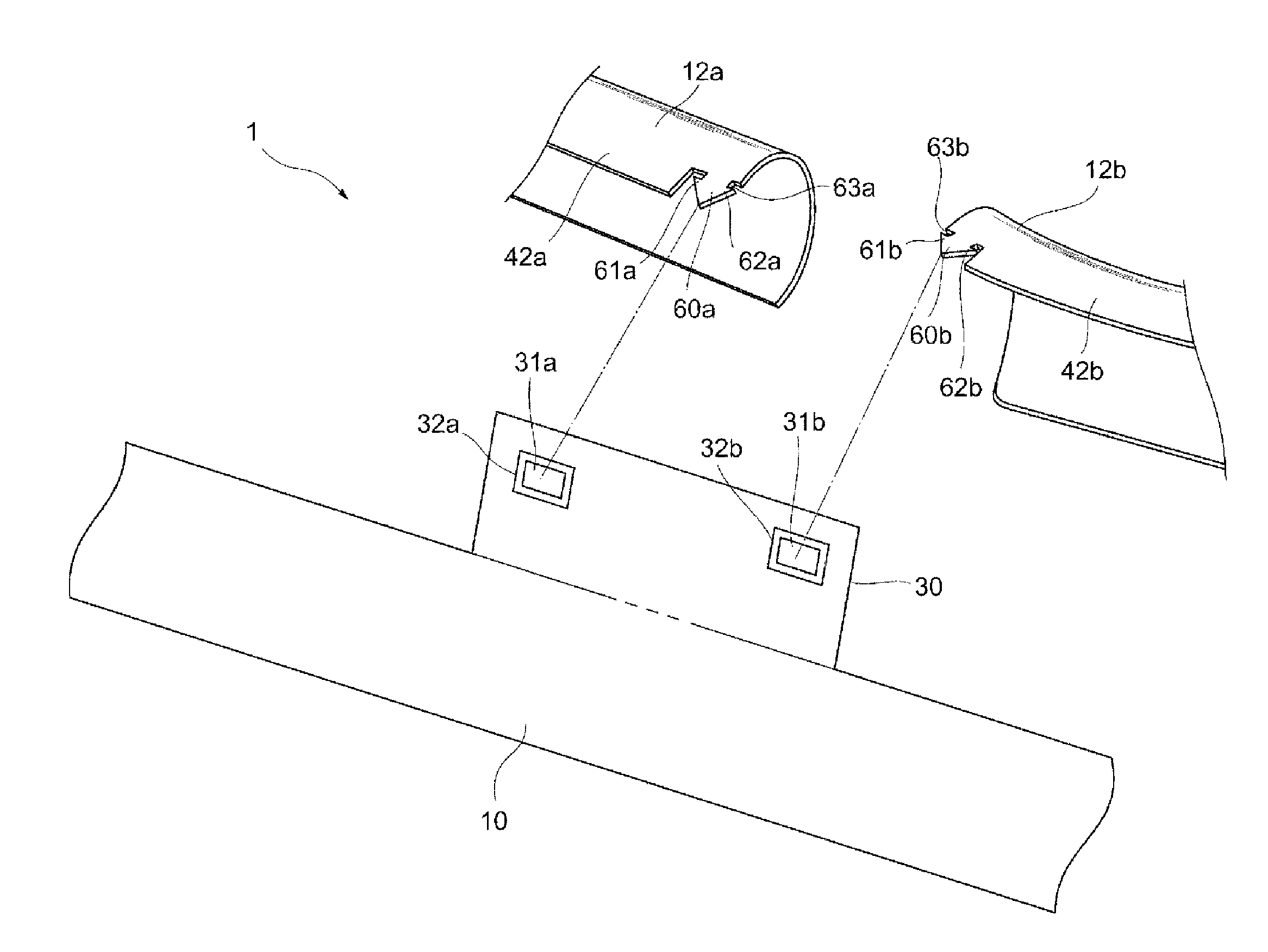
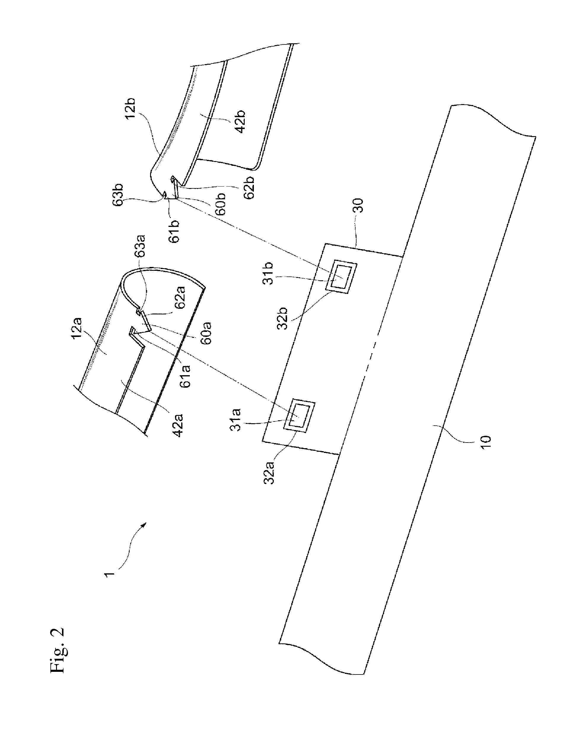
This airbag device includes a first protective cover and a second protective cover which store and protect an airbag. The airbag has a tab formed between the first protective cover and the second protective cover so as to protrude outward approximately in parallel with a longitudinal direction of the airbag. The tab has one end connected to the first protective cover and the other end connected to the second protective cover.

Description

BACKGROUND[0001]1. Field of the Invention[0002]The present invention relates to an airbag device attached to a roof side rail of a vehicle.[0003]2. Description of Related Art[0004]A vehicle airbag device in which an airbag is deployed in a curtain form from a roof side rail of the vehicle in order to prevent the head portion of an occupant from colliding with a side window or the like in the event of a side crash is known. Such an airbag device is also referred to as a curtain airbag device.[0005]In a curtain airbag device, an airbag is folded in a long and thin manner and is stored in a protective cover that is attached to a roof side rail of a vehicle. Airbags and protective covers are often disposed along the entire roof side rail in a front-rear direction of a vehicle in order to protect an occupant on a rear seat as well as an occupant on a front seat.[0006]As a result, since the entire protective cover is long, it is not desirable to form the protective cover as an integral bo...

Claims


Application Information

Patent Timeline
IPC IPC(8): B60R21/213B60R21/215
CPCB60R21/215B60R21/213
Inventor BEPPU, YOSHINORI
Owner AUTOLIV DEV AB
Learn More