Ultra high power single mode fiber laser system

Active Publication Date: 2015-02-26
IPG PHOTONICS CORP
View PDF0 Cites 0 Cited by
  • Summary
  • Abstract
  • Description
  • Claims
  • Application Information

AI Technical Summary

Benefits of technology

[0023]A further aspect of the disclosure includes pumping high power MM pump light into the large-diameter core end of the rod fiber. The pump light is characterized by a numerical aperture NAp lower than that of the core NAc which is substantially equal to or greater than 0.1. The counter-propagating direction, specified above NA of pump light and large mode field diameter of the FM provide favo

Problems solved by technology

Yet the power scaling of modern high power fiber laser systems is far from satisfying ever increasing industry demands.
Currently, advances in this field are primarily constrained by limitations in maximum extractable energy, and the onset of nonlinear effects.
The deleterious nonlinear effects and particularly stimulated Brillouin scattering (SBS) and stimulated Raman scattering (SRS) rob power from the signal and can cause catastrophic damage.
However, the core cannot be limitlessly increased.
While this is permissible, core size is then constrained by unavoidable but undesirable energy transfer among modes.
Unfortunately, as Aeff increases, neff decreases and at a certain point the mode coupling cannot be avoided.
An additional problem with large Aeff designs in all applications of high power lasers and amplifiers involves spatially transforming and focusing the device output.
Because of multiple fiber components, splice losses may be unforgivably high.
Furthermore, manufacturing the multicomponent system, as discussed above, is time inefficient and thus costly.
Still further, low threshold of NLEs and bending losses may still be unacceptable.
An open-end structure of fiber ro

Method used


Image

  • Ultra high power single mode fiber laser system
  • Ultra high power single mode fiber laser system
  • Ultra high power single mode fiber laser system

Examples


Example

[0031]Reference will now be made in detail to embodiments of the invention. Wherever possible, same or similar numerals are used in the drawings and the description to refer to the same or like parts or steps. The drawings are in simplified form and are not to precise scale. Unless specifically noted, it is intended that the words and phrases in the specification and claims be given the ordinary and accustomed meaning to those of ordinary skill in the fiber laser arts. The word “couple” and similar terms do not necessarily denote direct and immediate connections, but also include mechanical optical connections through free space or intermediate elements.

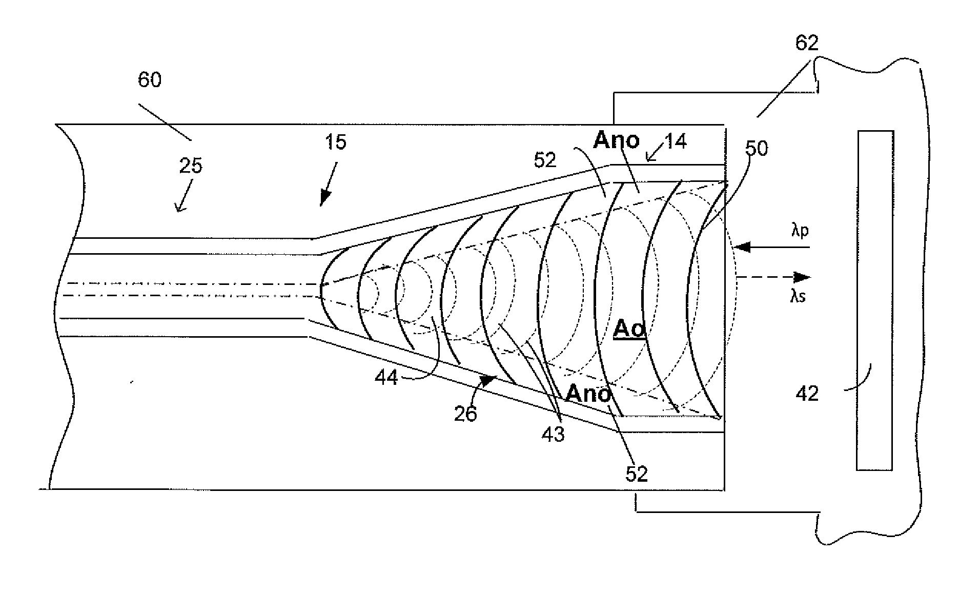
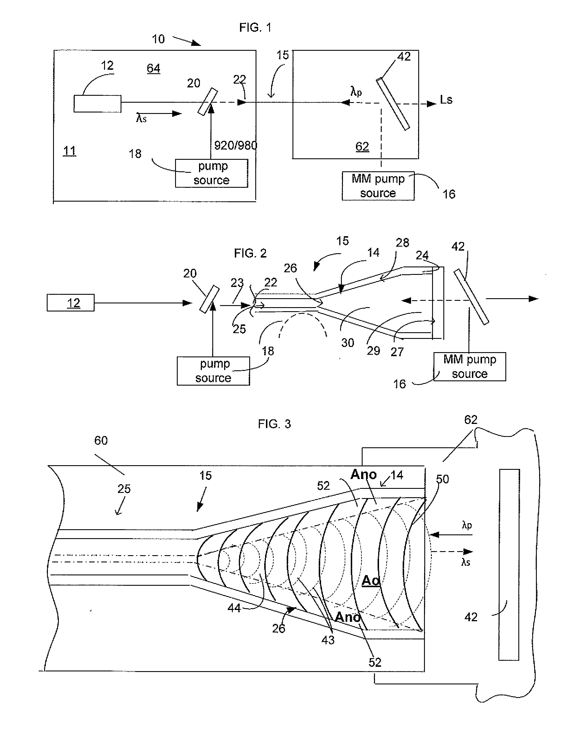
[0032]FIG. 1 illustrates a highly diagrammatic view of an ultra-high power laser system 10 configured with a main console 11, laser head assembly 62 spaced from main console 11 and unconfined booster 15 which extends between the console and laser head assembly over free space and is enclosed within a protective jacket 62 (FIG. 3) tha...


PUM


Abstract

An ultra-high power fiber laser system includes a single-piece fiber booster configured with fiber and straight short rod fiber portions which have in common a core configured with a numerical aperture equal to or higher than 0.1 and doped with ions of one or more rare earth elements across the entire cross-section thereof. The rod fiber portion is structured with a short length not exceeding about a few tens of centimeters and has a generally frustoconical cross-section expanding from the uniformly configured fiber portion. The core extending along the fiber portion is capable of supporting either a SM or a very low number of HOMs guided along the core in a propagating direction and coupled into the small diameter end of the rod fiber's frustoconically-shaped core. The opposite, large-diameter end of the frustoconical core supports multiple modes with a fundamental mode overlapping at least about 0.652 of the cross-section area of the core along the entire length thereof. The disclosed power system further includes a pump source emitting high power multi-mode pump light which is coupled into the large-diameter end of the core in a counter propagating direction with aNA of at most equal to the NA of the core. The pump is configured to emit pump light with such a density that while amplification of the fundamental mode continues in the overlapped area of the core, a peripheral non-overlapped area of the core is bleached. As a consequence, the disclosed system emits signal light in substantially a fundamental mode with an average power of several kWs in a CW regime or peak power of about one or more GWs in a pulsed regime of the system's operation.

Description

BACKGROUND OF THE DISCLOSURE[0001]1. Field of the Disclosure[0002]The disclosure relates to ultra-high power fiber laser systems emitting a MW-level peak and kW-level average power output substantially in a fundamental mode. Particularly, the disclosure relates to a single mode fiber laser system with a booster stage configured with as an active multimode fiber which has a few centimeter-long output core region end-pumped in a counter-propagating direction.[0003]2. Prior Art[0004]The dramatic rise in output power from rare-earth-doped fiber sources over the past decade, via the use of double clad fibers led to a range of fiber-laser system with outstanding performance in terms of output power, beam quality, overall efficiency, and wavelength flexibility. Yet the power scaling of modern high power fiber laser systems is far from satisfying ever increasing industry demands.[0005]Currently, advances in this field are primarily constrained by limitations in maximum extractable energy, a...

Claims


Application Information

Patent Timeline
IPC IPC(8): H01S3/094
CPCH01S3/094042H01S3/06745H01S3/06754H01S3/094011H01S3/094069H01S3/1618
Inventor GAPONTSEV, VALENTINSAMARTSEV, IGOR
Owner IPG PHOTONICS CORP
Why Eureka
Try Eureka