
Piezoelectric valve, and optical particulate matter sorter provided with air-blowing means that uses piezoelectric valve

a piezoelectric valve and optical particulate technology, which is applied in the direction of valve operating means/releasing devices, mechanical equipment, gas current separation, etc., can solve the problems of inability to achieve stable separation, change in the amount of air ejected from the nozzle, and vibration of the valve body, etc., to achieve stable gas supply, simple circuit configuration, and high responsivity

Active Publication Date: 2015-03-05
SATAKE CORP +1
View PDF11 Cites 6 Cited by
  • Summary
  • Abstract
  • Description
  • Claims
  • Application Information

AI Technical Summary

Benefits of technology

The present invention provides a piezoelectric valve that can stably supply gas and has a high responsivity at the time of valve opening. This valve is inexpensive compared to traditional valves because it uses a single-level driving voltage. Optical particulate matter sorters using this valve can stably supply air and have a high responsivity at the time of valve opening, which makes them reliable for blowing off defective grains or achieving stable particulate matter separation. The driving unit of the piezoelectric valve generates a signal with a pre-pulse and a main pulse, and applies a driving voltage to the piezoelectric element based on this signal to make it expand and open the valve. The method of driving the piezoelectric valve is simple and reduces costs compared to traditional valves.

Problems solved by technology

However, since the piezoelectric air valve moves a valve body via the displacement enlarging mechanism, the optical particulate matter sorter has a problem that, in case of long gas ejection time, the valve body vibrates and the amount of air ejected from the nozzle changes, and stable separation cannot be achieved.
However, the piezoelectric valve has a problem that it has a significantly low responsivity at the time of valve opening compared with the case where a single-level rectangular driving voltage is applied to the piezoelectric element.
In addition, the piezoelectric valve has another problem that it is expensive because the driving device has a complicated circuit configuration compared with the case where a single-level driving voltage is applied to the piezoelectric element.

Method used


Image

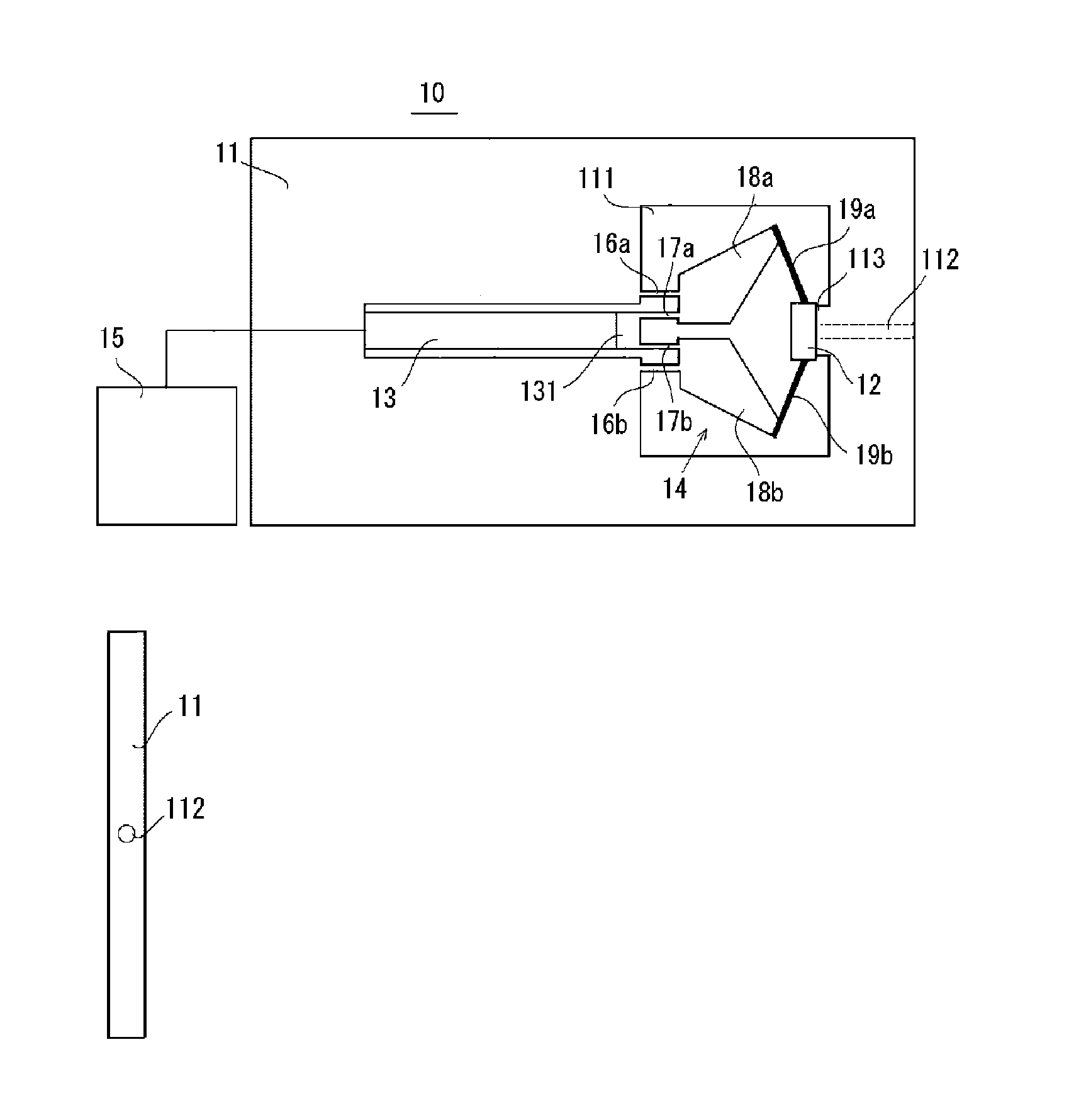
  • Piezoelectric valve, and optical particulate matter sorter provided with air-blowing means that uses piezoelectric valve
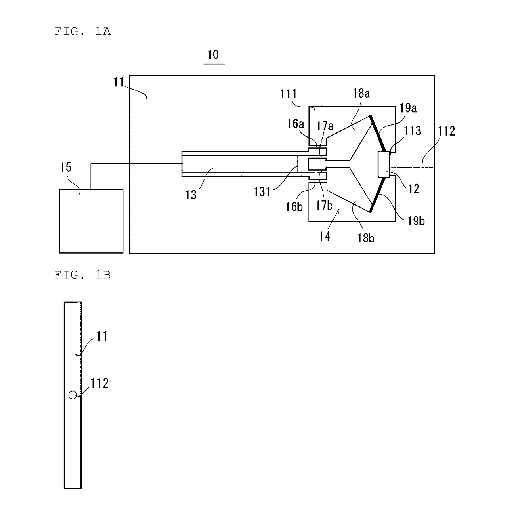
  • Piezoelectric valve, and optical particulate matter sorter provided with air-blowing means that uses piezoelectric valve
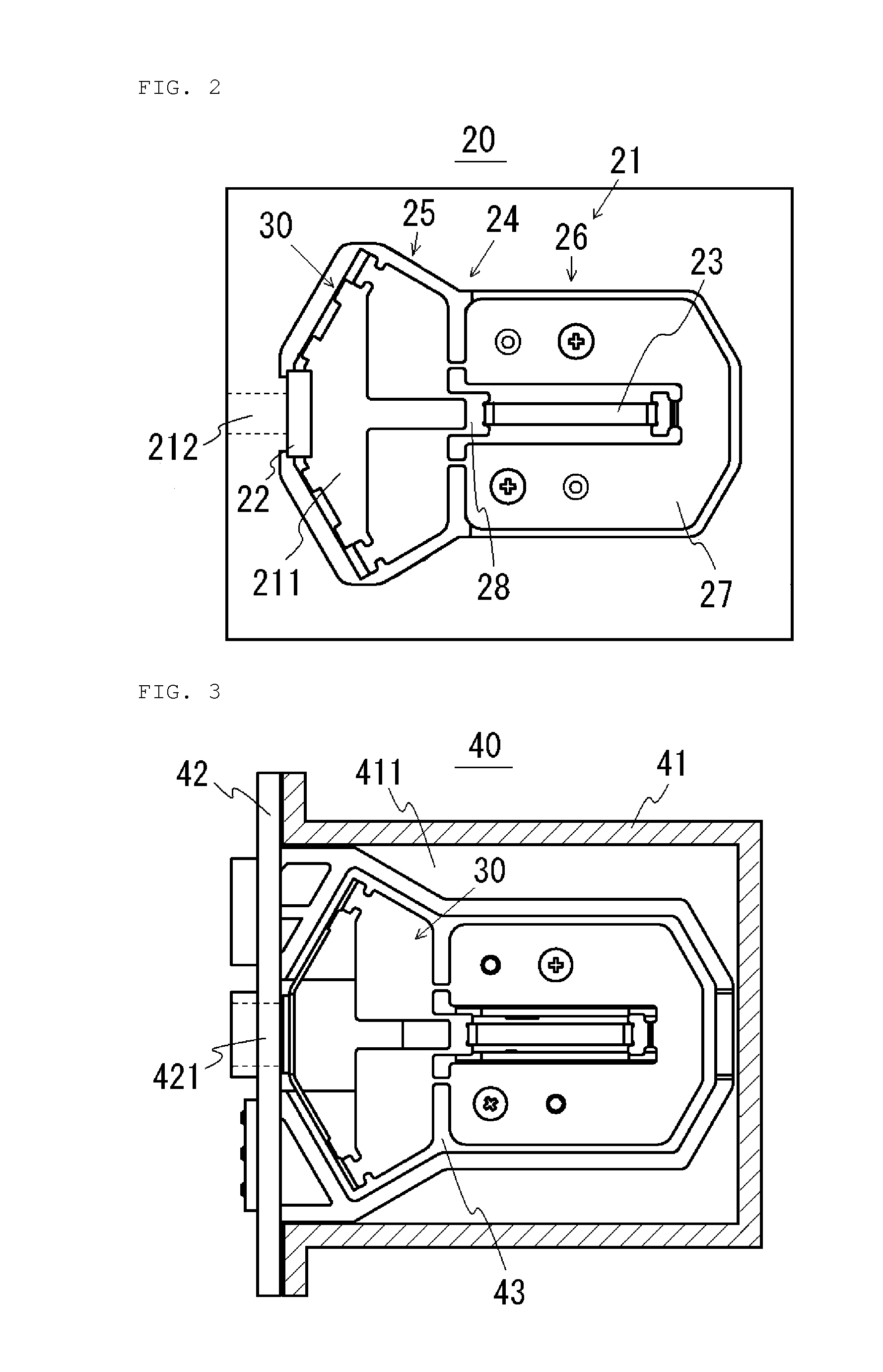
  • Piezoelectric valve, and optical particulate matter sorter provided with air-blowing means that uses piezoelectric valve

Examples


example

Pre-Pulse Signal

[0069]FIG. 4A is a block diagram showing a circuit configuration of the driving device of the piezoelectric valve according to the present invention, and FIG. 4B is a timing chart of signals that occur in the circuit and a voltage applied to the piezoelectric element.

[0070]As shown in FIG. 4A, the driving device of the piezoelectric valve according to the present invention applies a voltage to the piezoelectric element to charge the piezoelectric element to make the piezoelectric element expand by a signal generating unit 150 generating a charging signal A that comprises a pre-pulse and a main pulse (referred to as a pre-pulse signal hereinafter) and providing the pre-pulse signal to a charging driving circuit 151 as an input signal. The driving device make the piezoelectric element discharge to make the piezoelectric element compress by the signal generating unit 150 generating a discharging signal B and providing the discharging signal B to a discharging driving ci...


PUM


Abstract

A piezoelectric valve stably supplies gas even for a long gas ejection time, with a high responsivity to opening the valve, is provided. The piezoelectric valve, including a gas-pressure-chamber for receiving a compressed gas supplied from outside, a gas-discharge-channel through which the compressed gas is discharged from the gas-pressure-chamber, comprises: a valve body disposed in the gas-pressure-chamber and opens / closes the gas-discharge-channel; a piezoelectric element for producing a driving force to move the valve body as a displacement; a displacement-enlarging-mechanism for enlarging the displacement of the piezoelectric element to act on the valve body; and a driving unit having a signal-generating-unit for generating a signal comprising a pre-pulse and a main pulse and provides the signal generated by the signal-generating-unit to a driving circuit as an input signal to apply a driving voltage to the piezoelectric element to make the piezoelectric element expand and drive the valve body open.

Description

TECHNICAL FIELD [0001]The present invention relates to a piezoelectric valve that is opened and closed by expansion / compression displacement of a piezoelectric element, a method of driving the piezoelectric valve, and an optical particulate matter sorter provided with an air ejecting unit incorporating the piezoelectric valve.BACKGROUND ART [0002]A known conventional optical particulate matter sorter has a unit for ejecting air to separate grains, such as cereal grains or resin pellets, into non-defective grains (desired grains) and defective grains (unwanted grains) or remove foreign matters from the grains.[0003]The particulate matter sorter of this type separates grains by activating the above-described unit in response to a signal of detection of a defective grain or the like to eject air to blow off the defective grain when the grain is falling from an end part of a conveyor path along a predetermined trajectory.[0004]The particulate matter sorter ejects air to blow off defecti...

Claims


Application Information

Patent Timeline
IPC IPC(8): B07B11/02B07B4/00B07B11/04F16K31/00
CPCB07B11/02B07B11/04B07B4/00F16K31/007F16K31/004B07B4/02
Inventor ITO, TAKAFUMITAKEUCHI, TERUHIKOMATSUSHITA, TADASHICHEE, SZE KEATYANO, TAKESHIKAMIMA, TAKESHIHIGUCHI
Owner SATAKE CORP
Learn More