Crystal oscillator circuit having low power consumption, low jitter and wide operating range

a crystal oscillator and low power consumption technology, applied in the field of crystal oscillators, can solve the problems of large noise and large jitter in the circuit, and achieve the effect of good ability to suppress power supply nois

Active Publication Date: 2015-03-05
CAPITAL MICROELECTRONICS
View PDF3 Cites 22 Cited by
  • Summary
  • Abstract
  • Description
  • Claims
  • Application Information

AI Technical Summary

Benefits of technology

[0016]In the above embodiments, the self-adjuster isolates the power supply noise, and thus the crystal oscillator circuit has a very good ability to suppress the power supply noise.

Problems solved by technology

However, the circuit has disadvantages of large noise and large jitter.

Method used


Image

  • Crystal oscillator circuit having low power consumption, low jitter and wide operating range
  • Crystal oscillator circuit having low power consumption, low jitter and wide operating range
  • Crystal oscillator circuit having low power consumption, low jitter and wide operating range

Examples


Embodiment Construction

[0023]The technical solution of the present invention is further described below in detail with reference to the accompanying drawings and embodiments.

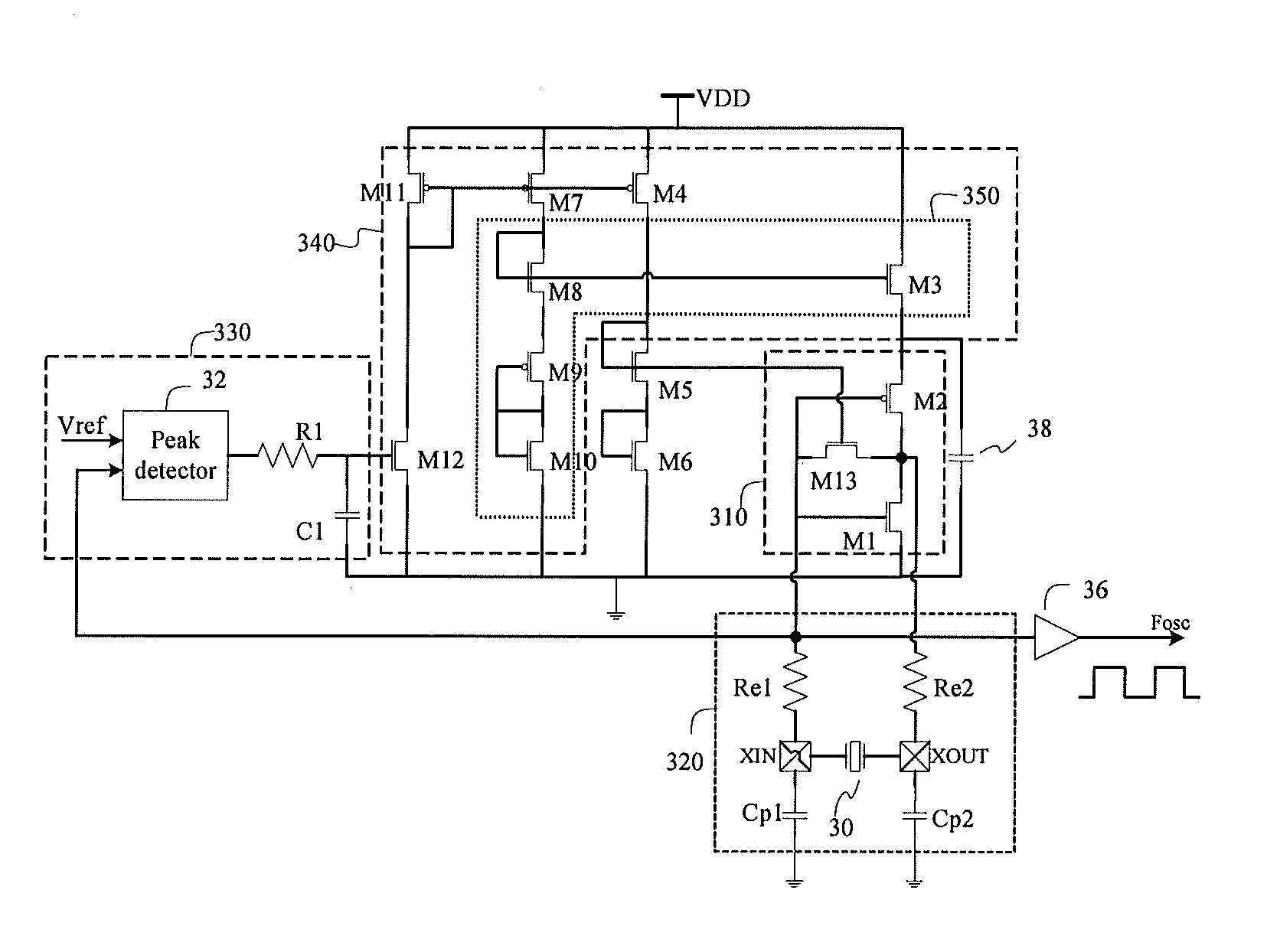
[0024]FIG. 3 illustrates a crystal oscillator circuit according to an embodiment of the present invention. As shown in FIG. 3, the crystal oscillator circuit includes an inverting amplification circuit 310, a crystal resonator circuit 320, a peak detection circuit 330, and a bias circuit 340. The bias circuit further includes a self-adjusting circuit 350.

[0025]The inverting amplification circuit 310 includes a PMOS transistor M2, an NMOS transistor M1 and an NMOS transistor M13. A drain of M1, a source of M2, and a drain of M13 are connected together, to form a first input end of the inverting amplification circuit 310, for receiving an oscillation signal; a gate of M1, a gate of M2, and a source of M13 are connected together, to form an output end of the inverting amplification circuit 310, for outputting an inverting amplified outpu...


PUM


Abstract

A crystal oscillator circuit includes: a crystal resonator circuit, generating an oscillation signal; an inverting amplification circuit, whose first amplifier input end is coupled to receive the oscillation signal, in which an inverting amplifier outputs an inverting amplified output signal; a bias circuit, having a bias circuit input end and a bias circuit output end, in which the bias circuit output end generates a bias circuit output signal controlled by the bias circuit input end, and the bias circuit output signal is coupled to a second amplifier input end; and a peak detection circuit, comparing the inverting amplified output signal with a reference signal, regulating a peak detector output signal, and feeding the peak detector output signal into the bias circuit input end, in which the bias circuit includes a self-adjusting circuit, for isolating a power supply from a second input end of the inverting amplifier.

Description

BACKGROUND[0001]1. Technical Field[0002]The present invention relates to a crystal oscillator, and in particular, to an amplitude controlled crystal oscillator having a peak detector, to adapt to a wider dynamic frequency range and a wider crystal indicator range.[0003]2. Related Art[0004]The oscillator is a component critical to the performance of modern electronic devices. Digital timepieces, computers, cameras, televisions, mobile phones, tablet computers, communications devices and the like all use a crystal oscillator to generate a desired clock signal.[0005]FIG. 1 illustrates a conventional crystal oscillator circuit. The oscillator circuit includes an inverting amplifier consisting of a PMOS transistor M2, a resistor R13 and an NMOS transistor M1 and a feedback network consisting of, for example, a quartz crystal, a capacitor Cp and a resistor Re. The feedback network outputs a feedback signal to an input end of the inverting amplifier, thereby forming a closed loop feedback ...

Claims


Application Information

Patent Timeline
Patent Type & Authority Applications(United States)
IPC IPC(8): H03B5/30
CPCH03B5/30H03B5/06H03B5/364H03B2200/0094
Inventor MAI, RIFENG
Owner CAPITAL MICROELECTRONICS
Why Eureka
Try Eureka