Indicating light for transportation

a technology for indicating lights and transportation, applied in the field of indicating lights, can solve the problems of irritating glare to human eyes, difficult to generate wide-angle (>120 degrees) and uniform illumination area, and difficult to achieve wide-angle uniform illumination without irritating glare by arrangement of led or optical design of lid covers, etc., to achieve wide-angle illumination and increase illumination area.

Inactive Publication Date: 2015-03-05
CHAO WEI PRECISION
View PDF8 Cites 5 Cited by
  • Summary
  • Abstract
  • Description
  • Claims
  • Application Information

AI Technical Summary

Benefits of technology

[0007]An objective of the present invention is to provide an indicating light for transportation, wherein the indicating light provides a curved or a flat surface light effect for overcoming the glare problem, achieving a wide angle illumination and increasing illumination area.
[0012]After the circuit board, the reflective layer and the light guide plate are sequentially mounted together, and the LEDs emit light toward the edge of the light guide plate. The light of the LEDs is guided into the light guide plate and the directivity of the light is changed by the indication portion to produce a surface light effect. Therefore, the illuminating angle and illuminating area will be increased, and the glare problem will also be mitigated.

Problems solved by technology

The LEDs have characters of small beam angle and high directionality to enhance efficiency of light concentrating and get high luminance However, in another aspect, the LEDs will easily cause irritating glare to human eyes and are difficult to generate a wide-angle (>120 degrees) and uniform illumination area.
For the design of traditional LED light, it is still difficult to get a uniform illumination of a wide angle without irritating glare by arrangement of LED or optical design of lid covering.

Method used


Image

  • Indicating light for transportation
  • Indicating light for transportation
  • Indicating light for transportation

Examples


Embodiment Construction

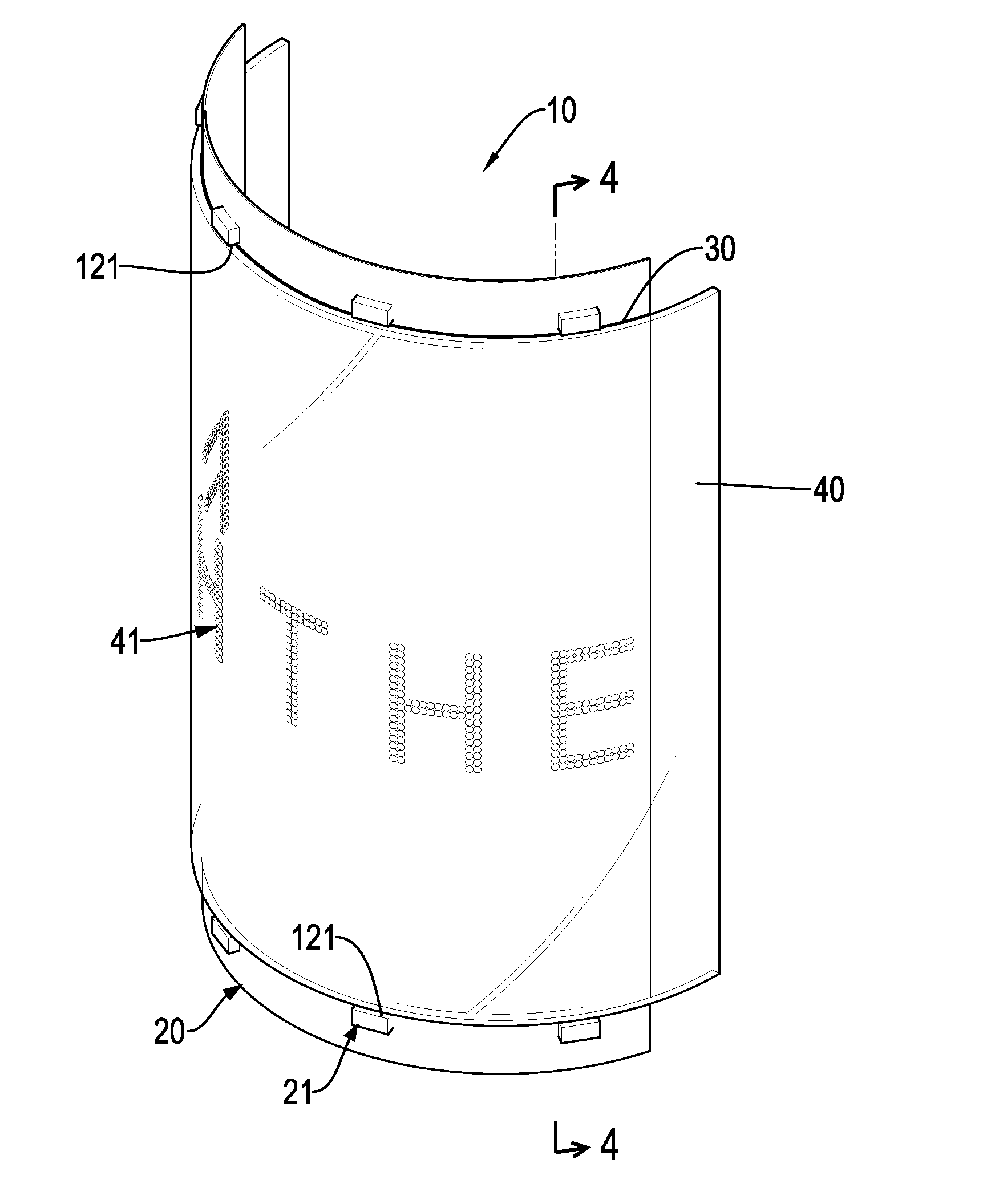
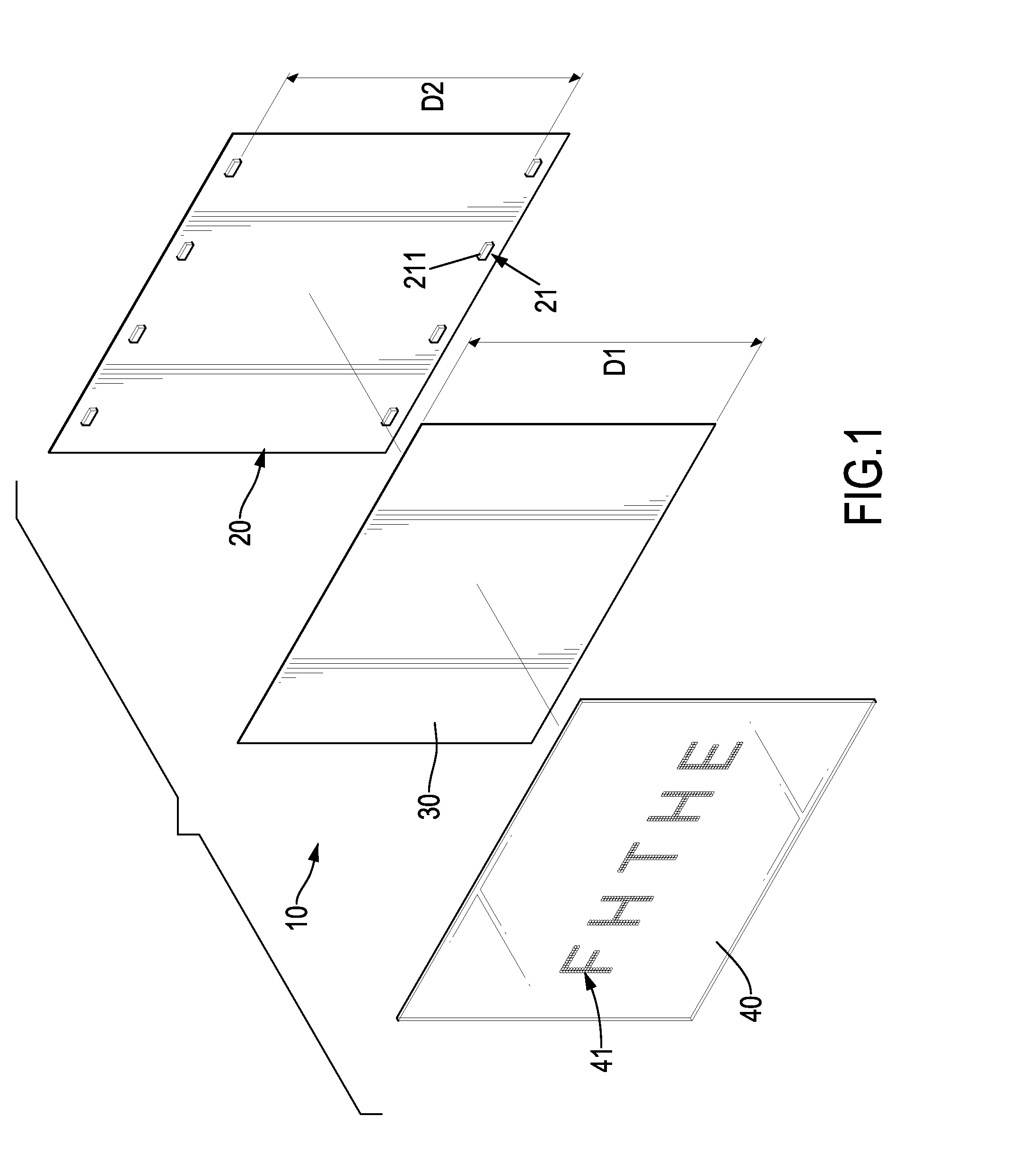
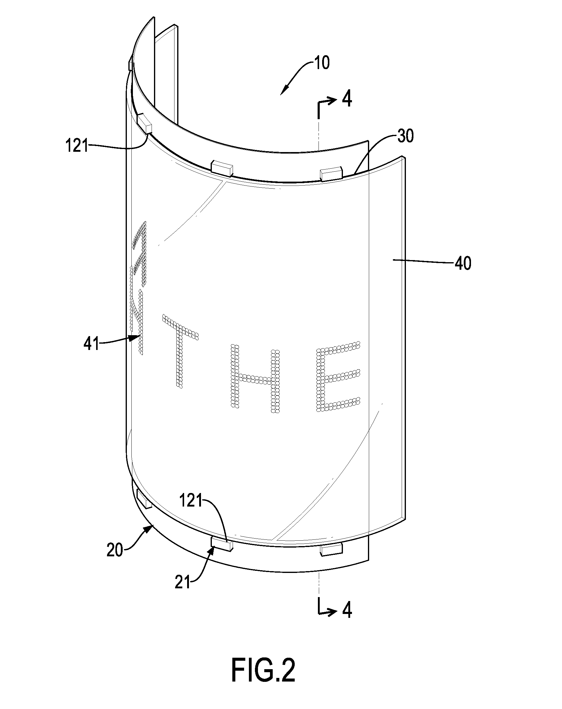
[0022]With reference to FIGS. 1 to 3, a first embodiment of an indicating light 10 of the present invention comprises a circuit board 20, a reflective layer 30 and a light guide plate 40. The reflective layer 30 and the light guide plate 40 are sequentially attached to the circuit board 20 and are sheet-shaped. As shown in FIG. 1, the circuit board 20, the reflective layer 30 and the light guide plate 40 are flat sheets. As shown in FIGS. 2 and 3, the circuit board 20, the reflective layer 30 and the light guide plate 40 may have flexibility and are in forms of curved sheets. For example, the circuit board 20, the reflective layer 30 and the light guide plate 40 can be bent to have an S-shaped cross section, a V-shaped cross section, a U-shaped cross section or a circular cross section.

[0023]The circuit board 20 is rectangular and has a surface, two long edges and two short edges. Multiple LEDs 21 are mounted on the surface of the circuit board 20 and controlled by the circuit board...


PUM


Abstract

An indicating light for transportation has a circuit board, a reflective layer and a light guide plate sequentially attached. Multiple LEDs are mounted on the circuit board and emit light. The light guide plate has an inner surface and an outer surface, wherein at least one indicating portion is formed on the inner surface for reflecting or refracting light of the LEDs to the outer surface. The reflective layer further prevents light leakage. Therefore, the indication portion generates a surface light effect for reducing glare and providing an enlarged illuminating area.

Description

BACKGROUND OF THE INVENTION[0001]1. Field of the Invention[0002]The present invention relates to an indicating light, and more particularly to an indicating light for transportation.[0003]2. Description of the Prior Art[0004]With the advantage of low power consumption, LEDs have been popularly applied on different objects in people's lives, for example, LED indicating lights for bicycles. The LEDs have characters of small beam angle and high directionality to enhance efficiency of light concentrating and get high luminance However, in another aspect, the LEDs will easily cause irritating glare to human eyes and are difficult to generate a wide-angle (>120 degrees) and uniform illumination area. Therefore, the LED light often utilizes multiple LEDs arranged in a circular shape to increase the uniform illumination of a wide angle.[0005]In addition to changing the arrangement of the LEDs, as the LED light usually has a transparent lid covering and protecting the LEDs, the illuminati...

Claims


Application Information

Patent Timeline
Patent Type & Authority Applications(United States)
IPC IPC(8): F21V8/00B62J6/00F21S8/00F21K99/00
CPCG02B6/0055F21K9/52B62J6/00G02B6/0068B62J2300/008F21S8/036G02B6/006F21W2101/023F21Y2105/003G02B6/0073G09F13/18G02B6/0038G09F7/18G09F2007/1813G09F2007/1878G09F2013/185B62J6/01B62J50/26
Inventor LIAO, YUNG-YUANLIAO, CHAO-CHE
Owner CHAO WEI PRECISION
Why Eureka
Try Eureka