Connection structure for screw clamp terminal

Inactive Publication Date: 2015-03-05
YAZAKI CORP
View PDF8 Cites 19 Cited by
  • Summary
  • Abstract
  • Description
  • Claims
  • Application Information

AI Technical Summary

Benefits of technology

[0009]The present invention is devised in view of such technical problems and aims to provide a connection structure for a screw clamp

Problems solved by technology

However, the conventional connection structure for a screw clamp terminal causes problems such as increasing the size of the terminal 1 because of the formation of th

Method used


Image

  • Connection structure for screw clamp terminal
  • Connection structure for screw clamp terminal
  • Connection structure for screw clamp terminal

Examples


Embodiment Construction

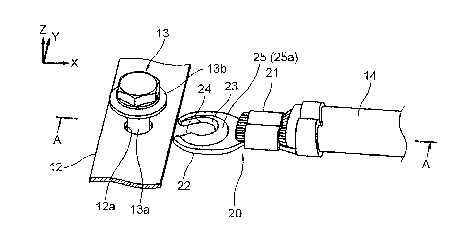
[0023]Embodiments of a connection structure for a screw clamp terminal according to the present invention will be described in details below with reference to the figures. In the present embodiment, the connection structure for a screw clamp terminal is applied to terminal connection in an electrical junction box (fuse box) by way of example. The configuration of the electrical junction box is well known per se, and a specific description of the electrical junction box will be omitted.

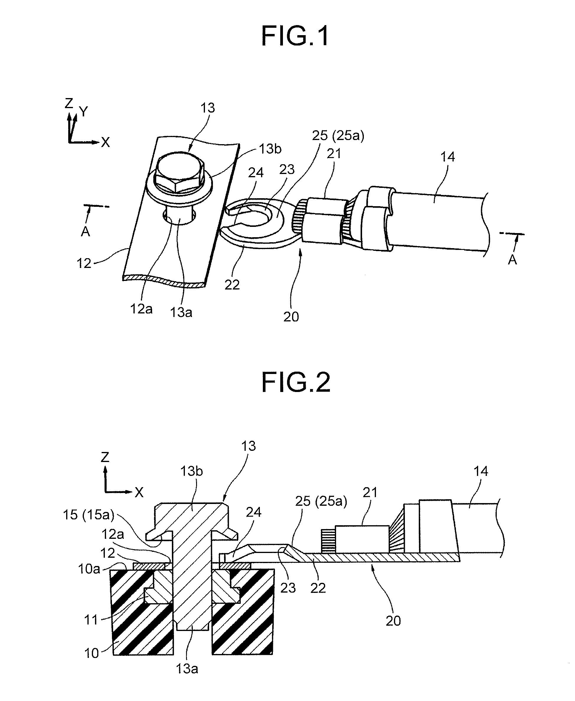
[0024]As illustrated in FIG. 1 and FIG. 2, a housing 10 of an electrical junction box is formed of an insulative resin material. A nut 11 is buried in the housing 10 such that the front end thereof faces a surface 10a in a state in which movement in the Z-axis direction and rotation around the Z-axis in the figures are restricted, that is, in a fixed state. A plate-shaped bus bar 12 serving as a member to be connected is arranged on the surface 10a of the housing 10. A hexagonal bolt (hereinafter simpl...


PUM


Abstract

An engagement projection having a convex conical surface is provided in an outer peripheral region of a bolt insertion hole in an electrical contact part of a terminal, while an engagement depression having a concave conical surface corresponding to the convex conical surface and capable of engaging with the engagement projection through the concave conical surface is provided on an inner surface of a head of a bolt disposed opposed to the engagement projection. The engagement projection and the engagement depression are engaged with each other during the fastening of the bolt.

Description

CROSS-REFERENCE TO RELATED APPLICATIONS[0001]The present application claims priority to and incorporates by reference the entire contents of Japanese Patent Application No. 2013-181737 filed in Japan on Sep. 3, 2013.BACKGROUND OF THE INVENTION[0002]1. Field of the Invention[0003]The present invention relates to a connection structure for a screw clamp terminal applied to, for example, an electrical junction box and fastened by a bolt to be electrically connected to a bus bar.[0004]2. Description of the Related Art[0005]A conventional connection structure for a screw clamp terminal is known, for example, in Japanese Patent Application Laid-open No. 2010-28919.[0006]Specifically, in the connection structure for a screw clamp terminal according to this patent literature, as illustrated in FIG. 6 and FIG. 7, a terminal 1 includes an electrical contact part 5 and a coupling section 6. The electrical contact part 5 is bifurcated approximately in the shape of letter U to form a bolt shaft ...

Claims


Application Information

Patent Timeline
IPC IPC(8): H01R4/30
CPCH01R4/305H01R11/12
Inventor HIRASAWA, HITOSHI
Owner YAZAKI CORP
Why Eureka
Try Eureka