Sanitary Wipe Dispensing Apparatus

a technology for dispensing apparatuses and sanitary wipes, which is applied in the field of dispensing apparatuses, can solve the problems of limited options and none of the placements are convenient for the user of wipes, and achieve the effect of minimal effor

Active Publication Date: 2015-03-26
DANGELO NICHOLAS
View PDF19 Cites 10 Cited by
  • Summary
  • Abstract
  • Description
  • Claims
  • Application Information

AI Technical Summary

Benefits of technology

[0006]It is an object of the invention to provide a personal sanitary wipe dispenser that places the wipes within easy reach, but with minimal effort and / or hardware required for mounting the dispenser.

Problems solved by technology

In a bathroom setting, however, there is limited space and therefore there are limited options where conventional sanitary wipe containers can be placed.
Countertops, shelves, and the bathroom floor are the favored locations for such containers housing sanitary wipes for bathroom use, yet none of those placements are convenient to the wipe user who is restricted to his location sitting on the toilet.
This inconvenience is one reason why personal sanitary wipes are not used in the bathroom setting more often despite the fact that the addition of a sanitary wipe in the bathroom cleaning process allows for more thorough cleansing.

Method used


Image

  • Sanitary Wipe Dispensing Apparatus
  • Sanitary Wipe Dispensing Apparatus
  • Sanitary Wipe Dispensing Apparatus

Examples


first embodiment

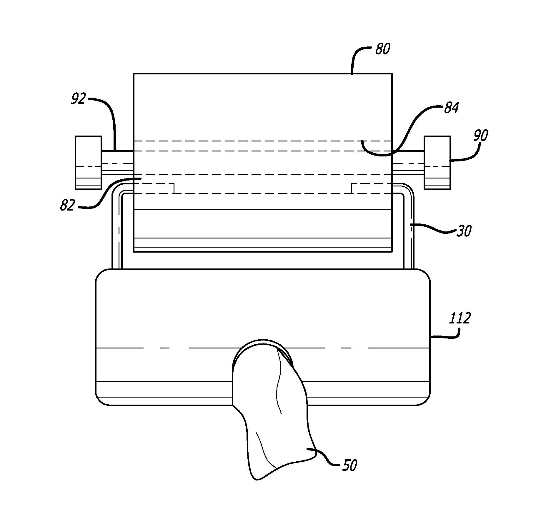
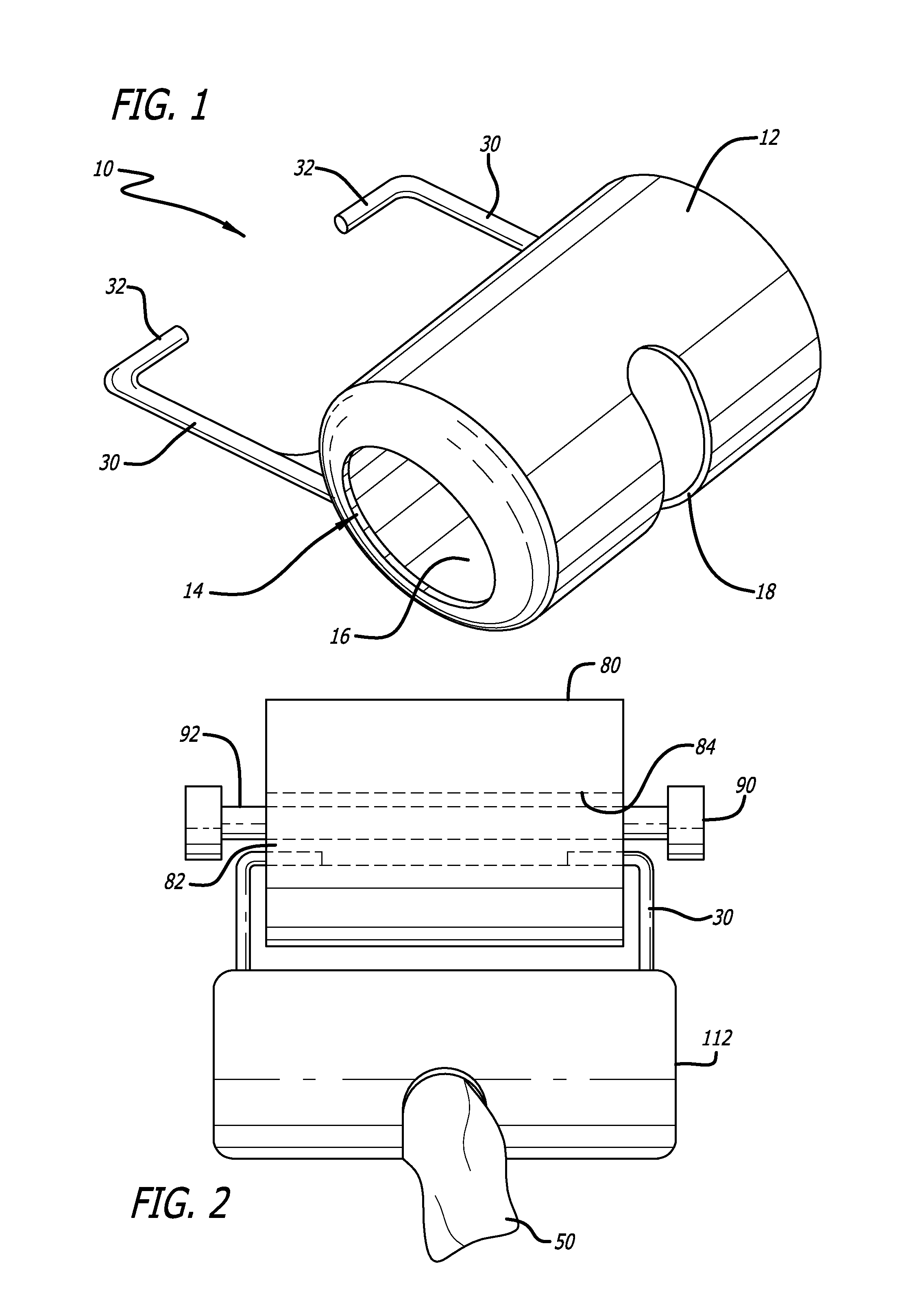
[0028]FIG. 1 is an oblique view of a dispenser according to the invention. Dispenser 10 includes a hollow housing 12 having an opening 14 into storage cavity 16 into which a pack of wet wipes is loaded and held within cavity 16. Individual ones of the wet wipes are dispensed serially through a second opening 18. Two generally vertically extending support arms 30 extend upward from housing 12. Each support arm 30 has a generally horizontally extending engagement arm 32 such that the two engagement arms 32 point toward and face each other. Support arms 30 may be made of a resilient material such as plastic, steel, plastic with spring steel embedded therein, or other resiliently bendable materials, such that the upper ends of arms 30 including engagement arms 32 may be bent apart elastically in order to slip engagement arms 32 over the ends of a standard toilet paper roll, and upon release the engagement arms 32 spring back inwardly to engage the axial hole or central cavity through th...

second embodiment

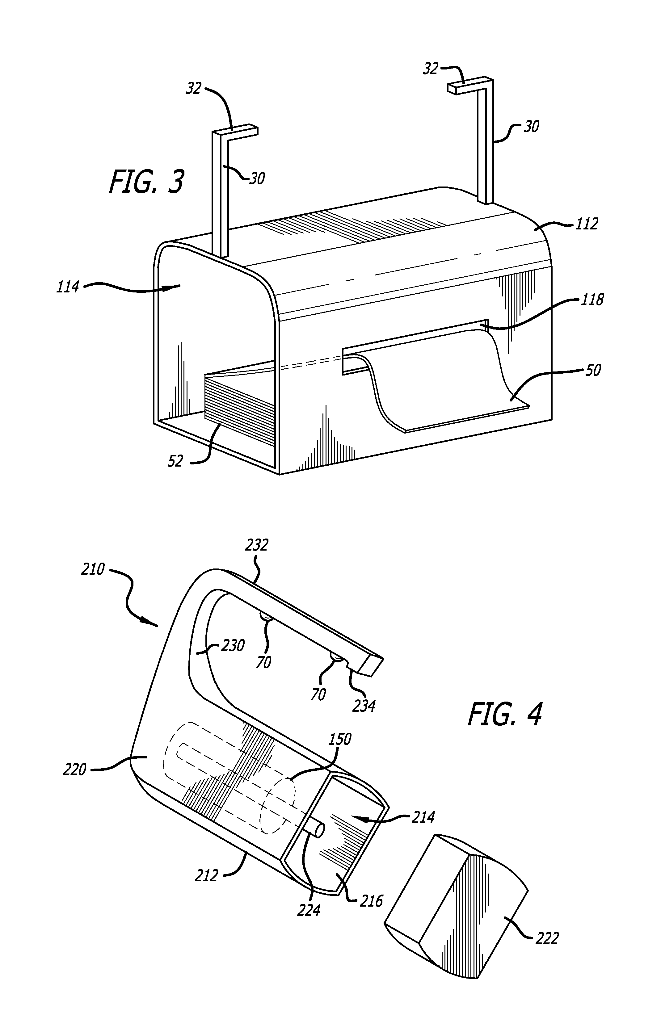
[0035]FIG. 3 is an oblique view of a dispenser according to a Stack 52 of wet wipes 50 can be seen. Stack 52 of wet wipes is loaded into housing 112 through loading opening 114, and the first wet wipe 50 is fed through the dispensing opening 118. Thereafter individual wipes 50 are serially dispensed to the user as a user pulls on them.

third embodiment

[0036]FIG. 4 is an oblique view of a third embodiment, with the dispensing opening 118 omitted for clarity of illustration. The dispensing opening 118 could be placed in virtually any location on the housing and be aligned in any orientation. As with the previous embodiments dispenser 210 has a housing 212 having a wet wipe loading opening 214, a cavity 216 which receives and stores the wet wipes, a dispensing opening through which the wipes are dispensed, and optionally a removable lid 222 or a hinged lid. The dispense opening can be located on the bottom, sides, or even on the top of the housing.

[0037]In this embodiment the dispenser 210 employs only a single engagement arm 232 to suspend the housing 212 below a toilet paper roll 80. The single engagement arm 232 preferably extends all the way through the toilet paper core tube, and is preferably 12-18 cm long for doing so. A downward projection 234 extends downwardly from the distal end of engagement arm 232 to abut up against th...


PUM


Abstract

A dispenser for personal sanitary wipes is suspended below a toilet paper roll by hooking into one or both sides of the core tube of a toilet paper roll at the same time that the toilet paper roll is mounted on a toilet paper spindle. In order to reduce friction as the toilet paper roll rotates, the dispenser may have wheels or rollers mounted on arm(s) that extend into the core tube.

Description

CROSS-REFERENCE TO RELATED APPLICATIONS[0001]This application claims priority from U.S. provisional patent application Ser. No. 61 / 881,780 filed Sep. 24, 2013.1. FIELD OF THE INVENTION[0002]This invention relates to the field of sanitary wipes. More particularly, this invention relates to the field of dispensers for personal sanitary wipes.2. DESCRIPTION OF RELATED ART[0003]Sanitary wipes have become a much more visible personal hygiene option over the last decade as an additional form of personal cleansing, household cleaning, anti-bacterial defense, and other uses. Such wipes are sometimes comprised of air-laid paper where the fibers are carried and formed into the structure of paper by air. These wipes are typically pre-moistened with any of a number of liquids, softeners, lotions, medications, anti-bacterial solutions, etc. to be used for personal hygienic purposes. Such wipes are accordingly sometimes referred to as “moist towelettes” or “wet wipes.”[0004]Conventionally, these ...

Claims


Application Information

Patent Timeline
Patent Type & Authority Applications(United States)
IPC IPC(8): A47K10/42
CPCA47K10/426A47K2010/3233A47K2010/3266A47K10/38A47K2010/326
Inventor D'ANGELO, NICHOLAS
Owner DANGELO NICHOLAS
Why Eureka
Try Eureka