
Method and apparatus for filtering an image

a filtering apparatus and image technology, applied in image enhancement, image analysis, instruments, etc., can solve the problems of computational complexity and computation independence, and achieve the effects of minimal computational overhead, improved quality of final filter output, and maintained o(n) complexity

Inactive Publication Date: 2015-03-26
THOMSON LICENSING SA
View PDF1 Cites 0 Cited by
  • Summary
  • Abstract
  • Description
  • Claims
  • Application Information

AI Technical Summary

Benefits of technology

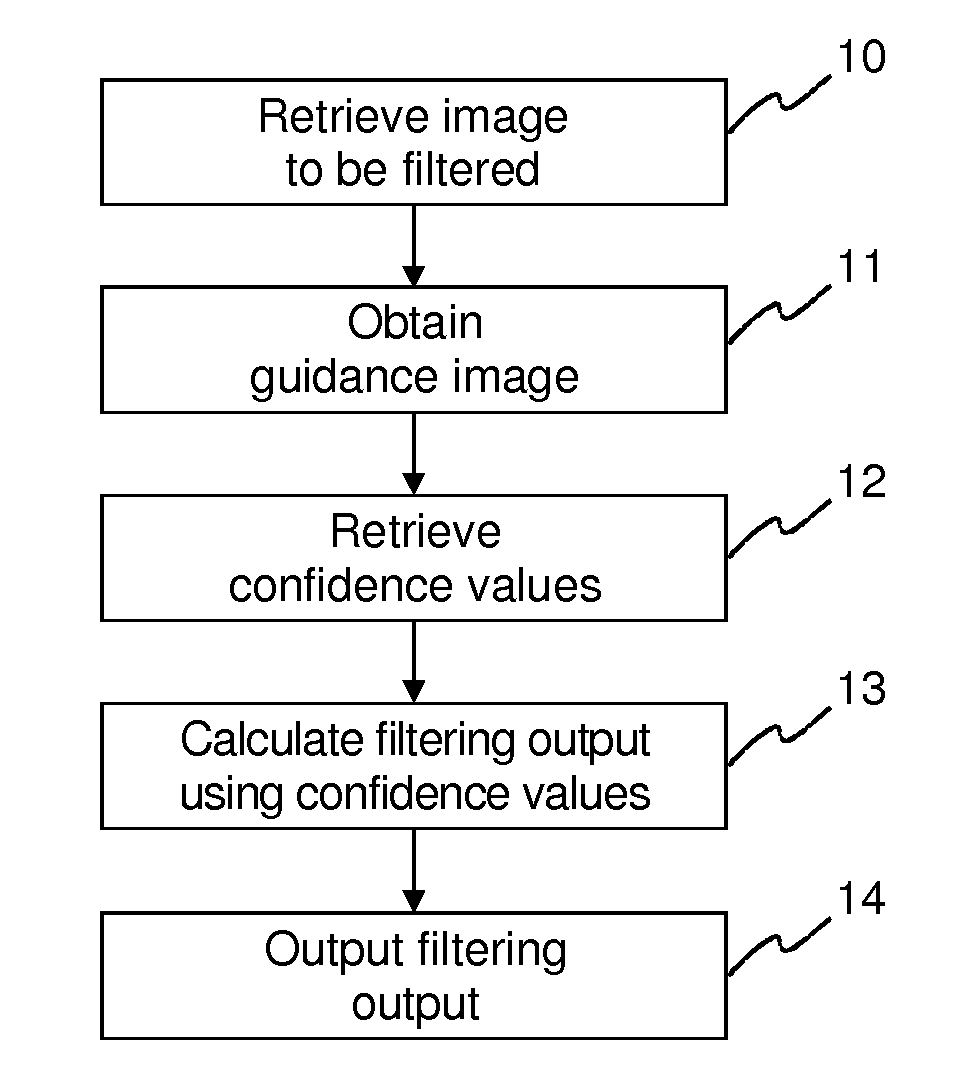
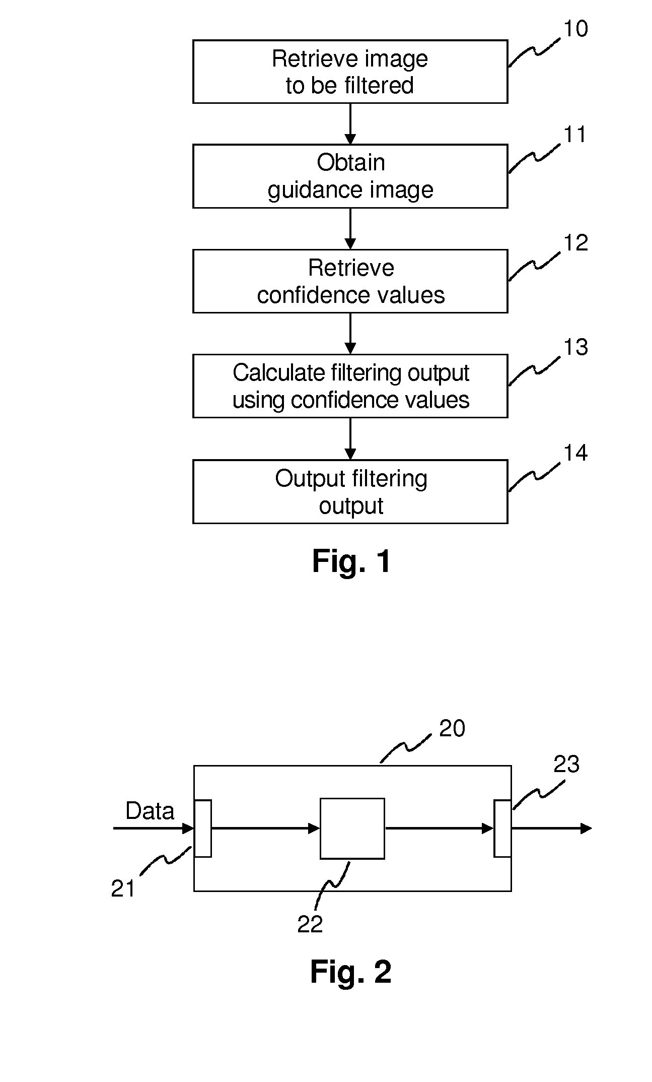
The proposed solution is a method to improve the quality of output from a smoothing filter called the Guided Image Filter. This is done by using confidence information associated with the input data. This method can be used in a variety of applications where noisy data is accompanied by confidence values, such as alpha matting, disparity estimation, and colorization. The method provides significant improvements in the quality of the final filter output with minimal computational overhead and while maintaining its O(n) complexity. In the case of alpha matting, the proposed method can improve the quality of the generated alpha mattes by about 28% on average when compared to the standard version of the filter. Additionally, the proposed method provides higher output quality compared to a different method called the confidence-aware Joint Bilateral Filter.

Problems solved by technology

Notably, this means that the computational complexity is independent of the chosen size of the filter kernel.
Besides potential gradient reversal artifacts, it suffers from computational complexity, especially for larger kernel sizes.

Method used


Image

  • Method and apparatus for filtering an image
  • Method and apparatus for filtering an image
  • Method and apparatus for filtering an image

Examples


case 1

[0020] The guidance image is a grey-scale image

[0021]The Guided Image Filter assumes that the filter output q is a linear transformation of the guidance image I in a window ωk centered at pixel k:

qi=akIi+bk, ∀i∈ωk,

where Ii denotes the pixel i in the Guidance Image, and ak and bk are some coefficients assumed to be constant in ωk. To determine the coefficients, the Guided Image Filter seeks a solution that minimizes the difference between the filter input p and its output q. The specific cost function is:

E(ak,bk)=∑i∈ωk((akIi+bk-pi)2+ɛak2),

where ε is a regularization parameter preventing the coefficient ak from becoming too large. The optimal coefficients can be computed via linear regression:

ak=Ip_k-I_kp_kσk2+ɛbk=p_k-akI_k.

[0022]Here,

Ip_k=1ω∑i∈ωkIipi

denotes the mean product of Ii and pi in ωk, Īk and σk2 are the mean and variance of I in ωk, |ω| denotes the number of pixels in ωk, and pk denotes the mean of p in ωk.

[0023]Since qi is contained in more than one window ωk, the Guided Im...

case 2

[0024] The guidance image is a 3-channel color image.

[0025]As for the grey-scale case, the Guided Image Filter assumes that the filter output q is a linear transformation of I in a window ωkcentered at pixel k:

qi=akTIi+bk, ∀i∈ωk,

where Ii now is a 3×1 vector representing the color of pixel i in the Guidance Image, and ak is a 3×1 coefficient vector for ωk. Again, ak and bk are assumed to be constant in ωk and are computed by linear regression as

ak=(Σk+εU)−1( Ipk−Īk pk)

bk= pk−akTĪk.

[0026]Σkdenotes the 3×3 covariance matrix of I in ωk. Its elements can be computed as

Σk(m,n)=1ω∑i∈ωkIi(m)·Ii(n)-1ω(∑i∈ωkIi(m))·1ω(∑i∈ωkIi(n)),

where |ω| denotes the number of pixels in ωk, and Ii(x) denotes the value of color channel x of I at pixel i.

[0027]As for the grey-scale case, since qi is contained in more than one window ωk, the Guided Image Filter expresses the final filter output as the averaged output over all windows that contain pixel i:

qi=1ω∑k:i∈ωk(akTIi+bk)=a_iTIi+b_i,wherea_i=1ω∑k:i∈ωkakb_i=...


PUM


Abstract

A method and an apparatus for filtering an image using a guided image filter are described. A filter computes a filtering output using a guidance image. For calculating the filtering output confidence values associated to a filter input are taken into account. A confidence-weighted averaging is performed using the confidence values.

Description

FIELD OF THE INVENTION[0001]The invention relates to a method and an apparatus for filtering an image, and more specifically to a method and an apparatus for filtering an image using a guided image filter.BACKGROUND OF THE INVENTION[0002]Recently a so-called Guided Image Filter has been developed as an edge-preserving smoothing filter. See He et al.: “Guided Image Filtering”, Proceedings of the 11th European conference on Computer vision (ECCV '10) (2010), pp. 1-14. Besides the input for the data to be filtered, the Guided Image Filter provides another input for a guidance image that drives the filtering process. It has been proven to be efficient in a wide range of applications, including alpha matting (see He et al.: “A Global Sampling Method for Alpha Matting”, Proceedings of the 2011 IEEE Conference on Computer Vision and Pattern Recognition (CVPR '11) (2011), pp. 2049-2056), and others. The Guided Image Filter has several key properties and advantages. A first advantage is the ...

Claims


Application Information

Patent Timeline
Patent Type & Authority Applications(United States)
IPC IPC(8): G06T5/00G06K9/46G06T5/20
CPCG06T5/002G06T5/20G06T2207/20182G06T2207/20028G06K9/4609G06T5/50G06T5/70
Inventor HOERENTRUP, JOBSTSCHLOSSER, MARKUS
Owner THOMSON LICENSING SA
Learn More