Center insulated concrete form

a technology of insulated concrete and center, which is applied in the direction of walls, building components, other domestic objects, etc., can solve the problems of high high cost of high cost of crane lifting the tilt-up slab wall in place, etc. problem, to achieve the effect of reducing the cost of energy and new building codes, and improving the safety of workers

Inactive Publication Date: 2015-04-02
MCCARY SR JOHN MILNER
View PDF0 Cites 2 Cited by
  • Summary
  • Abstract
  • Description
  • Claims
  • Application Information

AI Technical Summary

Benefits of technology

[0007]The invention is the manufactured assembly and process of using the concrete/cementous material flow through lattice panels to form and pour a center insulated concrete/cementous material poured wall. The center insulating solid panel, such as rigid insulation foam, is attached on both faces of the insulating solid panel to the flow through lattice panels by connecting cross members, or webs, keeping the concrete flow through lattice panels kept spaced apart and connected parallel to the solid insulation panel. Stencils or other surface material, such as “poly” sheeting, plywood and form liners, may be placed on the external surface of the lattice pane

Problems solved by technology

The higher cost of energy and new building codes have steadily pushed the poured concrete building industry to look for better ways to insulated structures.
The cost to crane lift

Method used


Image

  • Center insulated concrete form
  • Center insulated concrete form
  • Center insulated concrete form

Examples


Embodiment Construction

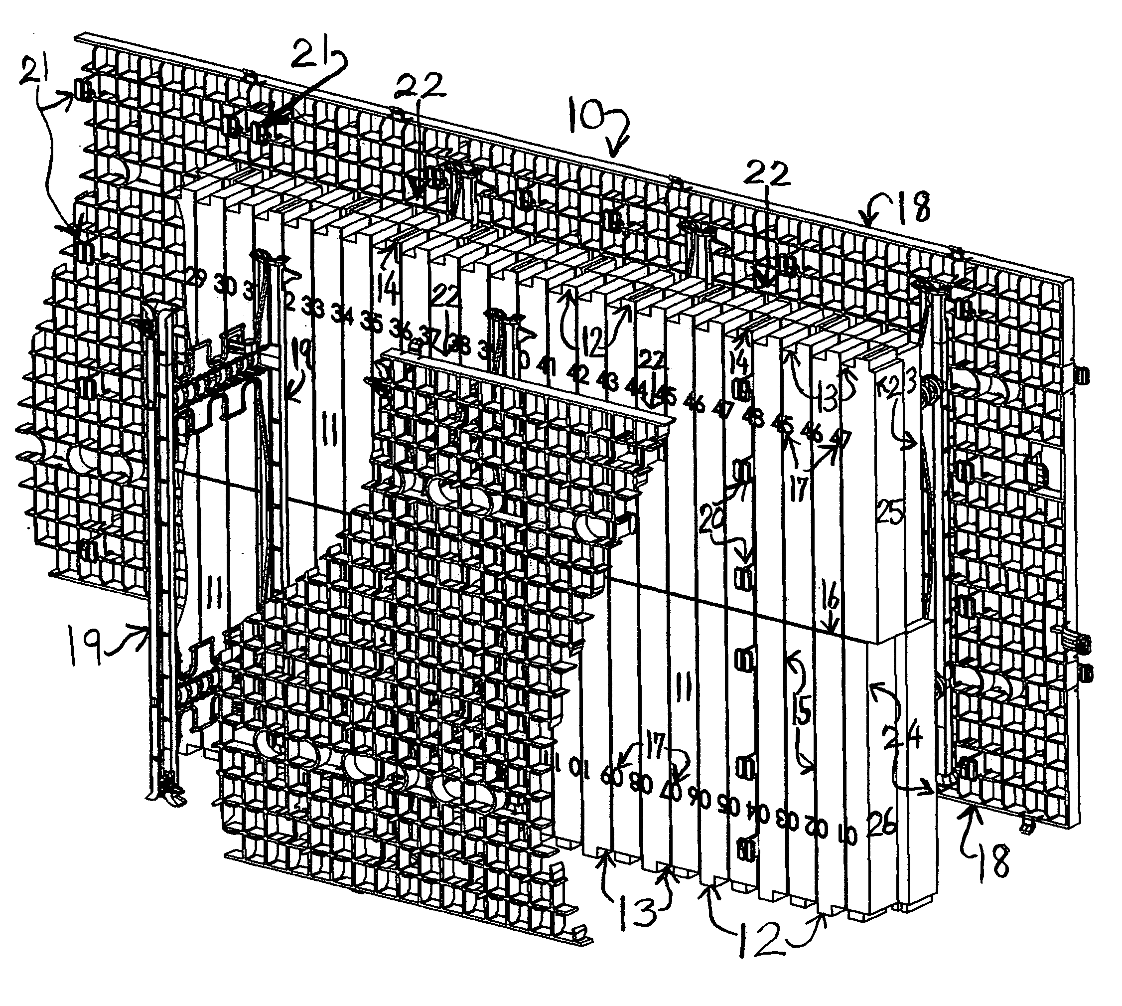
[0014]Shown in FIG. 1, in a front perspective view, is the center insulated concrete form 10. Shown is the solid insulation panel 11 with top and bottom edge attaching projections 12 and recesses 13. The compression slot projections 14 are shown. Vertical 15 and horizontal 16 marked line(s) are shown along with vertical line location numbers 17 on the solid insulation panel. The concrete flow through lattice panels 18 are shown attached to the connection web members 19 by the attaching points 20 on the face of the solid insulation panel and connecting webs attached to the lattice panels at attaching points 21. Two cavities 22 are formed between the solid insulating panel and the two lattice panels 18. The panel end upper row section 23 and the lower row section 24 are shown along with their projections 25 and recesses 26.

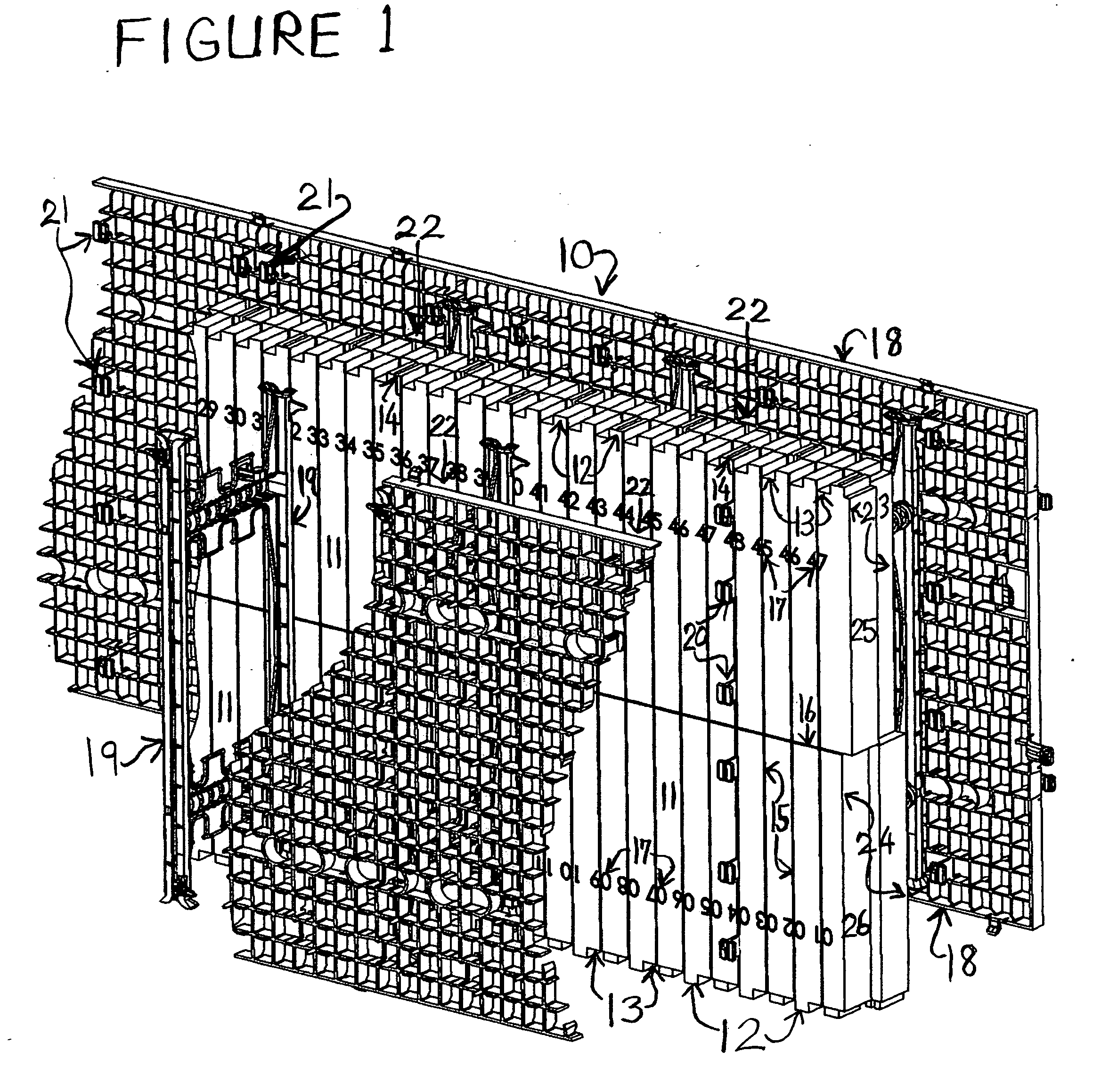
[0015]FIG. 2 shows in a side cross-sectional view a stacked panel center insulated concrete form 27 with the solid center insulation panels 28, the web connecters 2...


PUM

PropertyMeasurementUnit
Lengthaaaaaaaaaa
Flow rateaaaaaaaaaa
Sizeaaaaaaaaaa

Abstract

The invention is the manufactured assembly and process of using the concrete/cementous material flow through lattice panels to form and pour a center insulated concrete/cementous material poured wall. The center insulating solid panel, such as rigid insulation foam, is attached on both faces of the insulating solid panel to the flow through lattice panels by connecting cross members, or webs, keeping the concrete flow through lattice panels kept spaced apart and connected parallel to the solid insulation panel. Stencils, form liners or other shaping or decorative material can be attached to the exterior faces of the flow through lattice panels before pouring. Facial and/or decorative treatment can be performed on the wet, nearly dry or hardened lattice panel flow through concrete/cementous material.

Description

CROSS-REFERENCED TO RELATED APPLICATIONS[0001]This application makes reference to U.S. Pat. No. 8,153,046 dated Apr. 10, 2012 and U.S. application Ser. No. 13 / 358,676 filed Mar. 1, 2012.BACKGROUND OF THE INVENTION[0002]There have been recent advances and the need for poured concrete walls that have insulation as part of the concrete form assembly such as insulated concrete forms (I C F's) and rigid foam insulation being placed within wooden and metal concrete forms. In U.S. Pat. No. 8,153,046 and demonstrating further improvements in U.S. application Ser. No. 13 / 358,676 a poured concrete form is assembled and poured using flow through lattice panels connected to solid panels by connecting members. The solid panel could be an insulating panel, such as rigid foam insulation.[0003]The higher cost of energy and new building codes have steadily pushed the poured concrete building industry to look for better ways to insulated structures. In many segments of the poured concrete structure i...

Claims


Application Information

Patent Timeline
IPC IPC(8): B29D99/00
CPCB29D99/0021E04B2/8635E04B2/8658E04B2002/8688
Inventor MCCARY, SR., JOHN MILNER
Owner MCCARY SR JOHN MILNER
Why Eureka
Try Eureka