
Smart-home system facilitating insight into detected carbon monoxide levels

a technology of smart home and detection, applied in the direction of optical radiation measurement, electric/electromagnetic audible signalling, air quality improvement, etc., can solve the problems of alarm false, time-consuming, stressful, and potentially dangerous, and achieve the effect of facilitating provisioning, setup, configuration, control and/or managemen

Active Publication Date: 2015-04-09
GOOGLE LLC
View PDF20 Cites 151 Cited by
  • Summary
  • Abstract
  • Description
  • Claims
  • Application Information

AI Technical Summary

Benefits of technology

The patent describes a method to control a smart home using a computer or a smart device, like a smart thermostat. The smart device is equipped with technology that recognizes the user's face or creates a signature for them, allowing the device to provide limited control to guests who come without permission. This technology ensures that the smart home is secure and can only be controlled by registered users.

Problems solved by technology

This can be time-consuming, stressful, and potentially dangerous.
Oftentimes the alarm is false.
For example, smoke detectors located near bathrooms may mistake shower steam as smoke.
Similarly, smoke detectors located in or near kitchens may mistake steam from boiling water as smoke.
Also, smoke detectors located in or near kitchens may provide a large number of false alarms due to their over sensitivity to moderate smoke levels common to kitchens.
Disabled or otherwise ineffective hazard detectors result in preventable accidental home deaths.
For example, people die each year in home fires, such as fires caused by occupants who fall asleep while smoking cigarettes, because the hazard detectors in their homes were disabled, or because the hazard detectors malfunctioned or were improperly installed.

Method used


Image

  • Smart-home system facilitating insight into detected carbon monoxide levels
  • Smart-home system facilitating insight into detected carbon monoxide levels
  • Smart-home system facilitating insight into detected carbon monoxide levels

Examples


Embodiment Construction

[0039]The present invention will now be described in detail with reference to certain embodiments thereof as illustrated in the accompanying drawings. In the following description, numerous specific details are set forth in order to provide a thorough understanding of the present invention. It will be apparent, however, to one skilled in the art, that the present invention may be practiced without some or all of these specific details. In other instances, well known details have not been described in detail in order not to unnecessarily obscure the present invention.

Overview of the Smart-Home Environment

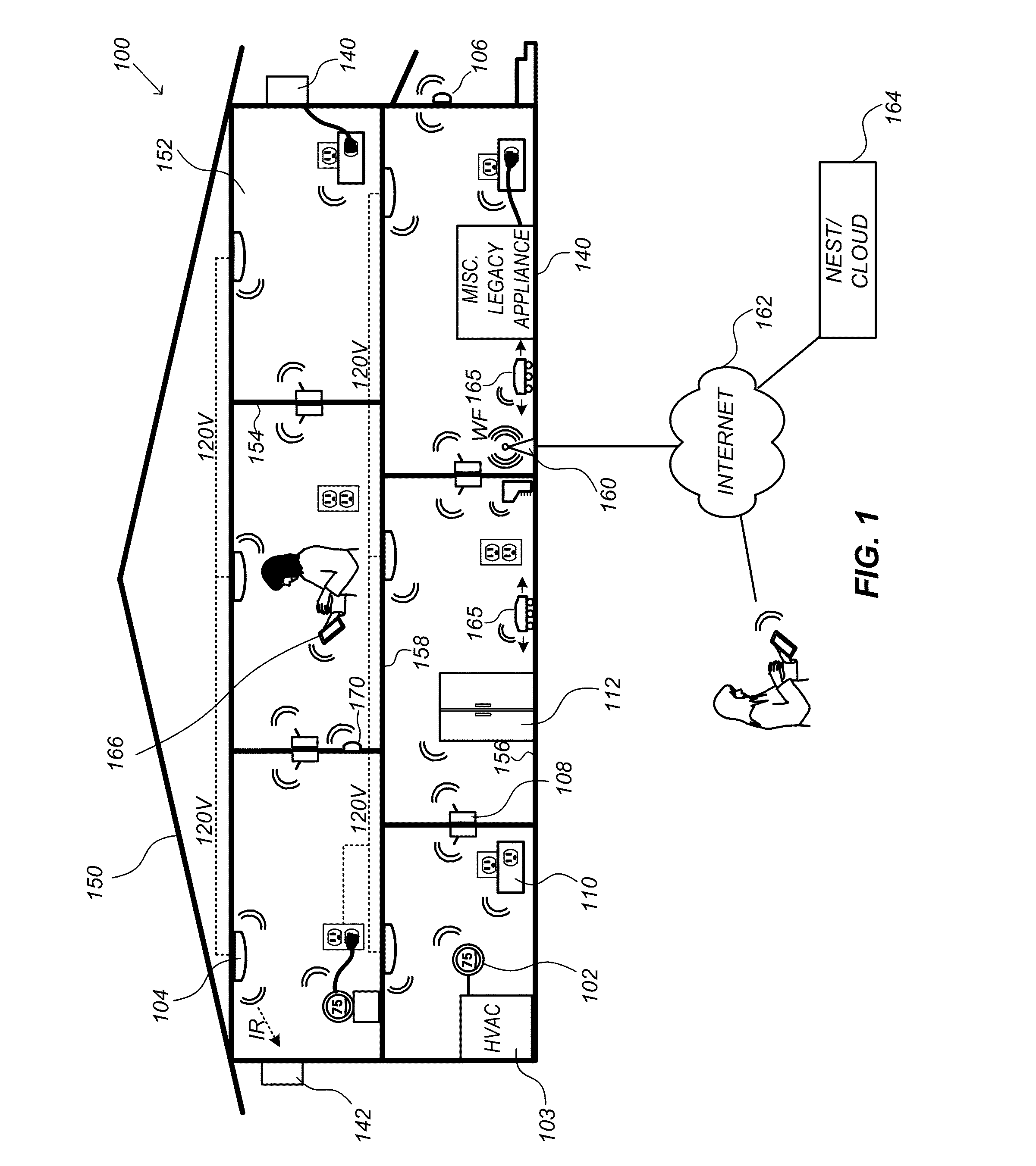
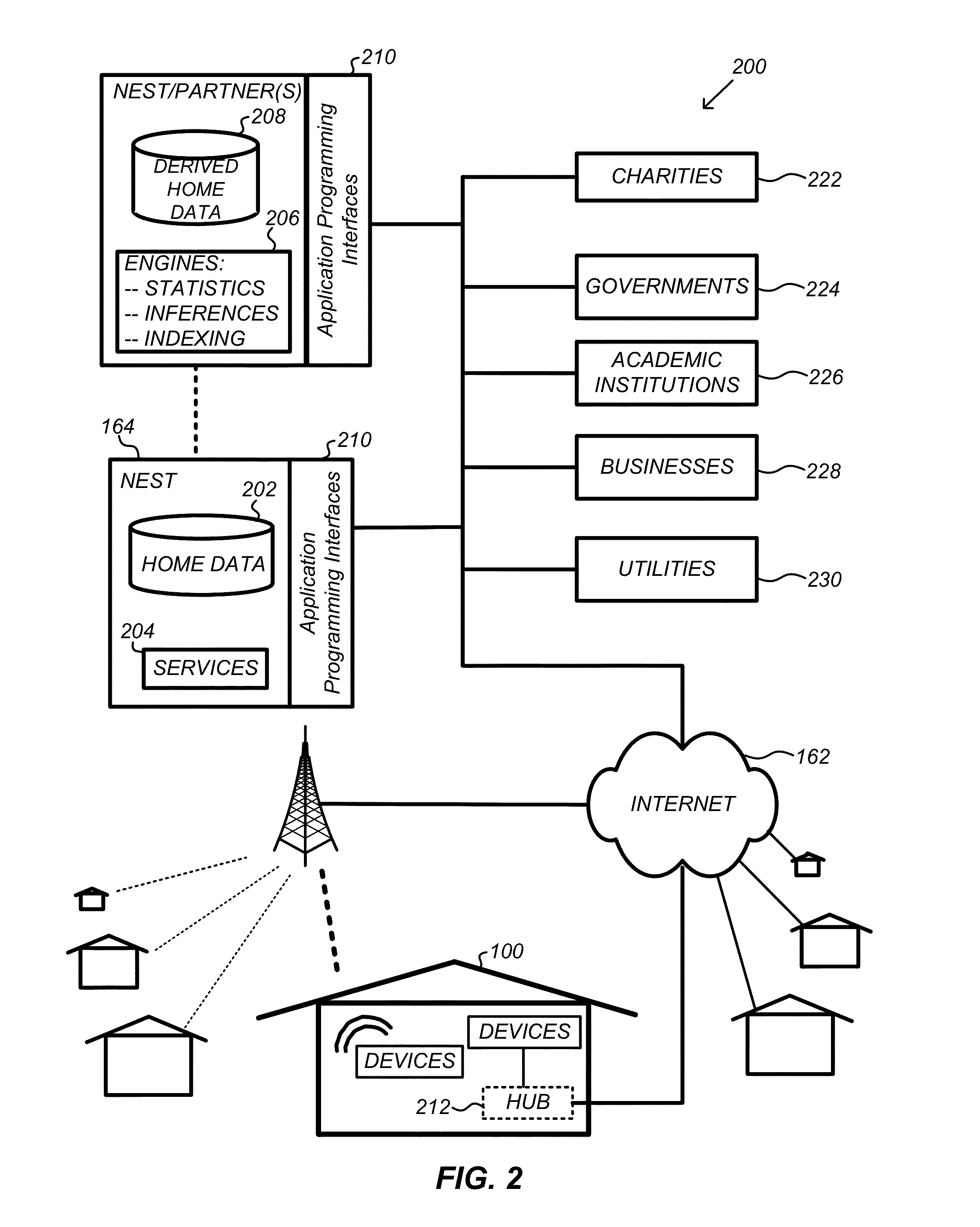
[0040]Provided according to one or more embodiments are methods and systems for setting up, controlling, and / or programming one or more of intelligent, network-connected, multi-sensing hazard detection units or smart hazard detectors. These smart hazard detectors may be configured and adapted to be implemented in a smart-home environment, seamlessly interacting with other devices in ...


PUM

PropertyMeasurementUnit
voltageaaaaaaaaaa
temperatureaaaaaaaaaa

Abstract

In an embodiment, a method determines one or more sources of carbon monoxide (CO) in a smart-home environment that includes a plurality of smart devices that have at least measurement and communication capabilities. The method includes measuring a level of CO in the smart-home environment to generate a CO measurement, and providing the CO measurement and one or more current characteristics of the smart-home environment, from one or more of the smart devices to an analyzing device. The method further includes evaluating, by the analyzing device and with the CO measurement and the current characteristics of the smart-home environment, a set of CO correlation scenarios that attribute generation of CO to a corresponding one of a set of specific sources, and selecting one or more of the specific sources as the most likely source of the CO, by aggregating results of the correlation scenarios.

Description

CROSS-REFERENCE TO RELATED APPLICATIONS[0001]This application claims the benefit of priority to U.S. Provisional Patent Application Ser. No. 61,887,969, filed 7 Oct. 2013, entitled “User-Friendly Detection Unit,” and U.S. Provisional Patent Application Ser. No. 61,887,963, filed 7 Oct. 2013, entitled “Hazard Detection in a Smart-Sensored Home.” The above-identified patent applications are hereby incorporated by reference herein in their entireties for all purposes.TECHNICAL FIELD[0002]This patent specification relates to systems, devices, methods, and related computer program products for providing hazard-detection objectives. More particularly, this patent specification relates to a plurality of devices, including intelligent, multi-sensing, network-connected hazard detection units or smart hazard detectors (e.g., smoke detectors, carbon monoxide detectors, etc.), that communicate with each other and / or with a central server or a cloud-computing system to provide any of a variety o...

Claims


Application Information

Patent Timeline
Patent Type & Authority Applications(United States)
IPC IPC(8): G01N33/00G01N27/12G01N27/02H05B44/00
CPCG01N33/004G01N27/121G01N33/0031G01N27/02G08B17/10G08B29/185G08B25/012G08B25/08F24F11/30G08B21/14H04L12/2818H04L12/2803F24F2120/10F24F11/33F24F11/46F24F11/58Y02A50/20H05B45/20H05B47/19G08B29/145G08B5/36H05B47/1975H05B47/1965H05B47/196H05B47/197H05B47/11H04M1/72445H05B45/10G06V20/46H04L67/54G08B25/008G08B21/18G08B3/10G08B5/22G08B21/12G08B29/02G08B29/04G08B25/002G08B29/26G08B17/117G08B21/182G08B29/22H04L12/282H04L67/025G01J1/4204G01V8/10G06T7/70G08B19/005H04L12/2809H04L67/10H04N7/183F24F11/34F24F11/75F24F11/89F24F11/70
Inventor PETERSON, KEVINSLOO, DAVIDMATSUOKA, YOKYWEBB, NICHOLAS UNGER
Owner GOOGLE LLC
Learn More