
Drive system for bed

a drive system and bed technology, applied in nursing beds, medical science, ambulance services, etc., can solve the problems of increasing complexity and cost in manufacturing such dual-drive wheel systems, unable to effectively manually maneuver the bed having the dual-drive wheel system, and increasing the difficulty of manual steering adjustments

Inactive Publication Date: 2015-04-09
GENDRON
View PDF14 Cites 19 Cited by
  • Summary
  • Abstract
  • Description
  • Claims
  • Application Information

AI Technical Summary

Benefits of technology

The present invention is about a patient bed with a single-wheel drive system and an improved trapeze boom. The bed has a frame with a mounting bracket and a sliding block. The drive system includes a motor mount assembly with an actuator and ground engaging wheels. A toggle mount assembly is connected to the frame and the motor mount assembly. A bariatric patient management system has a frame with casters and the drive system. The technical effects of this invention include improved maneuverability, reduced noise, and improved stability of the bed.

Problems solved by technology

Subsequently, bariatric beds having the dual drive wheel system cannot be manually maneuvered effectively.
The weight of the bariatric bed while carrying a patient makes manual steering adjustments increasingly difficult to perform when both drive wheels are engaged with a floor surface.
This often results not only in added complexity and cost in manufacturing such dual-drive wheel systems, but it also requires that the dual-wheel drive system have advanced controls such as a multi-axis joystick, adding even more complexity and cost to the system.
The position of the bed's headboard relative to the patient trapeze may limit access to the patient from a direction outside of and adjacent the headboard.
Furthermore, the multiple supports for the patient trapeze present an additional obstacle for a healthcare professional attempting to gain access to the patient from behind the headboard.

Method used


Image

  • Drive system for bed
  • Drive system for bed
  • Drive system for bed

Examples


Embodiment Construction

[0018]The following detailed description and appended drawings describe and illustrate various exemplary embodiments of the invention. The description and drawings serve to enable one skilled in the art to make and use the invention, and are not intended to limit the scope of the invention in any manner.

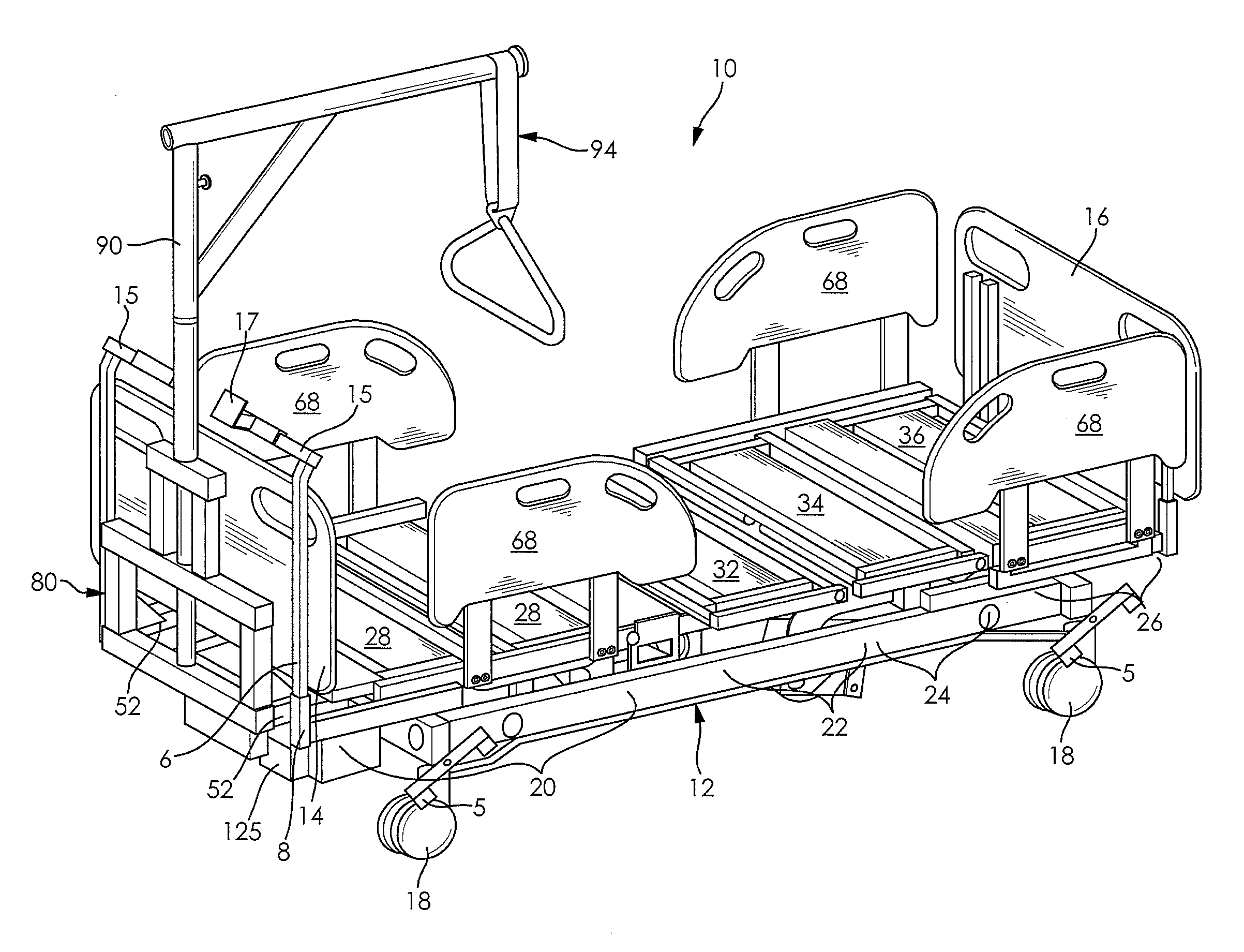
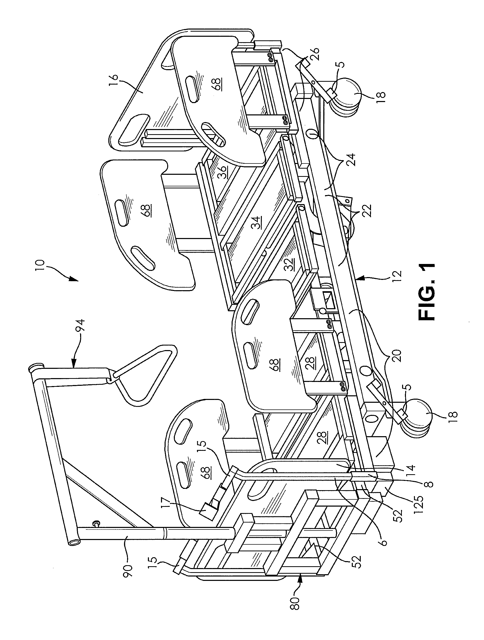
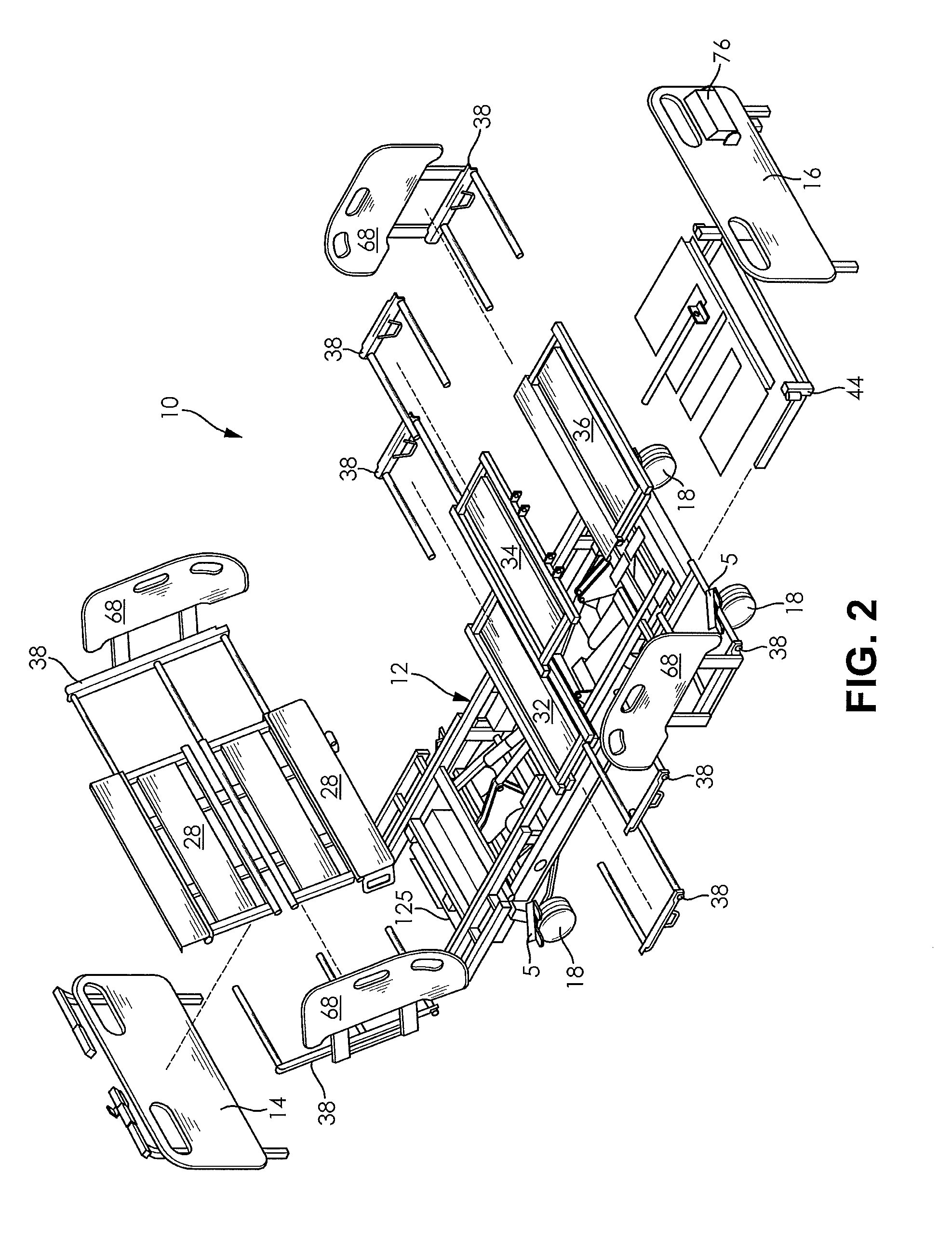
[0019]FIGS. 1-7 show an embodiment of a bariatric patient management system 10. The bariatric patient management system 10 includes a body supporting main frame 12, a headboard 14, a footboard 16, and ground engaging casters 18 for supporting a patient, as clearly illustrated in FIGS. 1-3. The bariatric patient management system 10 further includes a single-wheel drive system 110 and a trapeze support structure 80.

[0020]The main frame 12 can be of solid or split construction and includes a backrest section 20, a middle section 22, a leg section 24, and a foot section 26. The backrest section 20, the middle section 22, the leg section 24, and the foot section 26 cooperate to form a ma...


PUM


Abstract

A bariatric patient management system includes a single-wheel drive system having bi-directional variable speed control through use of a variable control joystick. The single-wheel drive system is disposed on an underside of the bariatric patient management system and engages a floor surface when the bariatric bed is in a lowermost position. The bariatric patient management system further includes a removable headboard having a disconnect feature for disconnecting the variable control joystick from the single-wheel drive system when the headboard is removed. A plurality of three-setting casters is used in conjunction with the single-wheel drive to allow the bariatric patient management system to be manually turned when transported from one location to another. The bariatric patient management system further includes an improved trapeze boom that allows for additional access to a patient adjacent the headboard of the bariatric patient management system.

Description

CROSS-REFERENCE TO RELATED APPLICATIONS[0001]This application claims priority to U.S. Provisional Application Ser. No. 61 / 887,056, filed Oct. 4, 2013, the entire disclosure of which is hereby incorporated herein by reference.FIELD OF THE INVENTION[0002]The present invention relates to a portable patient bed, and more particularly to a bariatric patient bed having a single-wheel drive system for transporting the bariatric patient bed.BACKGROUND OF THE INVENTION[0003]Bariatrics is typically defined as the branch of medicine concerned with the management of obesity and allied diseases. When working with patients in need of bariatric services and procedures, it has been found necessary to deal with persons weighing up to and exceeding one thousand pounds. Accordingly, it has become necessary to develop beds, stretchers, chairs, and / or tables capable of supporting the weight of persons weighing up to and exceeding one thousand pounds.[0004]When dealing with patients of an elevated weight...

Claims


Application Information

Patent Timeline
IPC IPC(8): A61G7/08A61G7/053A61G7/012A61G7/05
CPCA61G7/08A61G7/0506A61G7/0533A61G2203/14A61G2007/0528A61G2200/16A61G7/012A61G7/015A61G7/018A61G7/0528A61G7/108A61G2220/16
Inventor OTTENWELLER, PAULMARTIN, ISAAC W.
Owner GENDRON
Learn More