Suction roll device

a roll device and suction roll technology, applied in the direction of thin material processing, transportation and packaging, filament handling, etc., can solve the problems of clogging dust and chemicals, unable to uniformly impart winding tensile force to all the strip coils, and affecting the quality of the product, so as to achieve the effect of reliably winding up and ensuring gripping and conveying

Active Publication Date: 2015-04-16
JDC INC
View PDF7 Cites 10 Cited by
  • Summary
  • Abstract
  • Description
  • Claims
  • Application Information

AI Technical Summary

Benefits of technology

[0068]The suction roll device of the present invention is able to sufficiently grip and convey or control a variety of long materials without damaging them and also able to reliably wind them up.

Problems solved by technology

Where there is a failure in imparting an appropriate winding tensile force to the metal strip coil, the metal strip coil after processing is wound erroneously or an edge of the thus wound coil is made irregular, thereby exhibiting a poor appearance, which poses a problem.
However, in the above-described individual devices, on imparting a winding tensile force, abrasions and smears will adhere on the surface of the strip coil.
A problem is also posed such that no winding tensile force can be imparted uniformly to all the strip coils.
However, fine holes on the outer circumference of the roll are clogged with dust and chemicals.
Thus, it is necessary to clean the device in a short period of time, resulting in a decreased operating rate, which poses a problem.

Method used


Image

  • Suction roll device
  • Suction roll device
  • Suction roll device

Examples


Embodiment Construction

[0084]Hereinafter, a description will be given of an embodiment of the present invention by referring to drawings for the purpose of understanding the present invention.

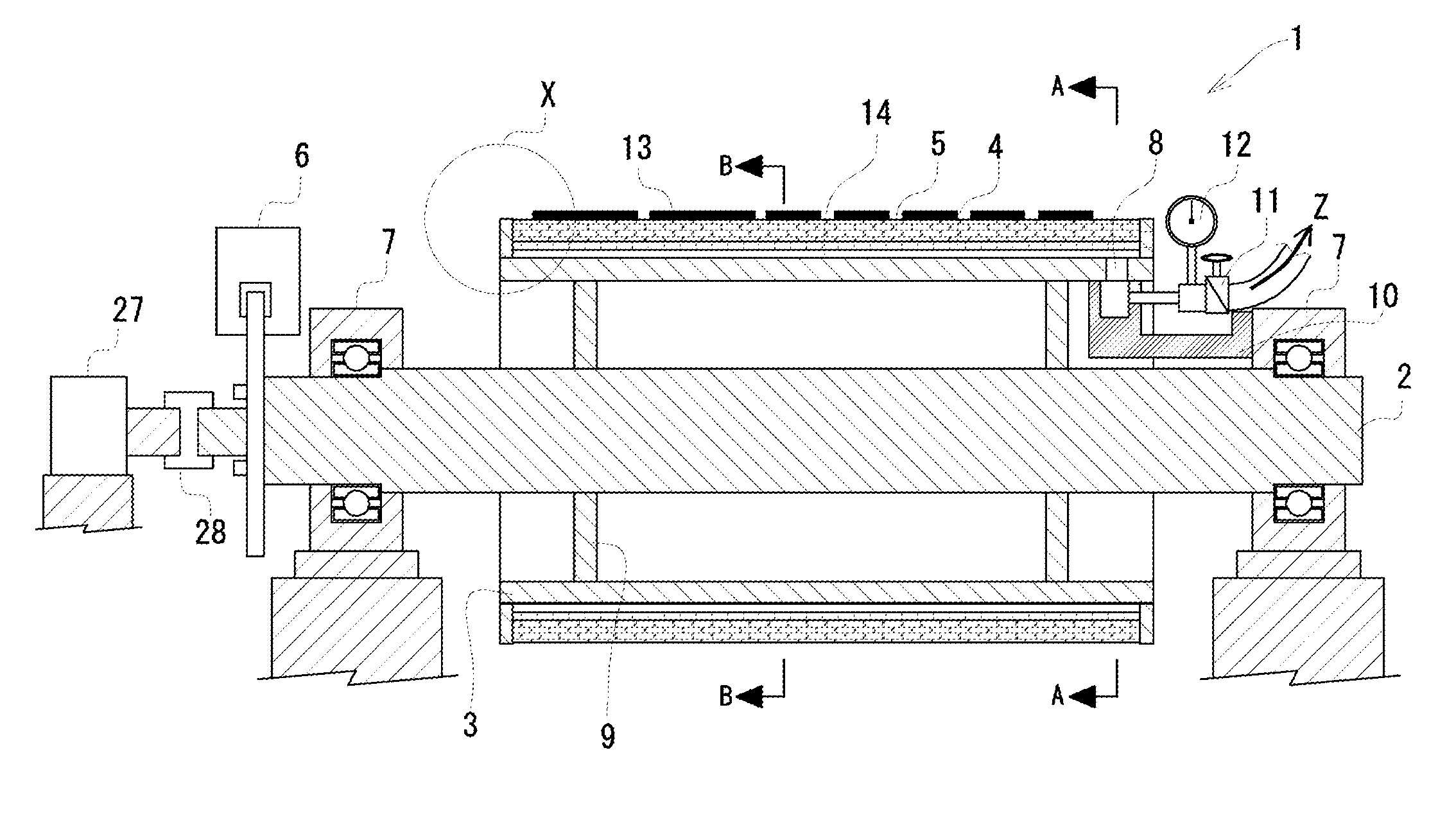
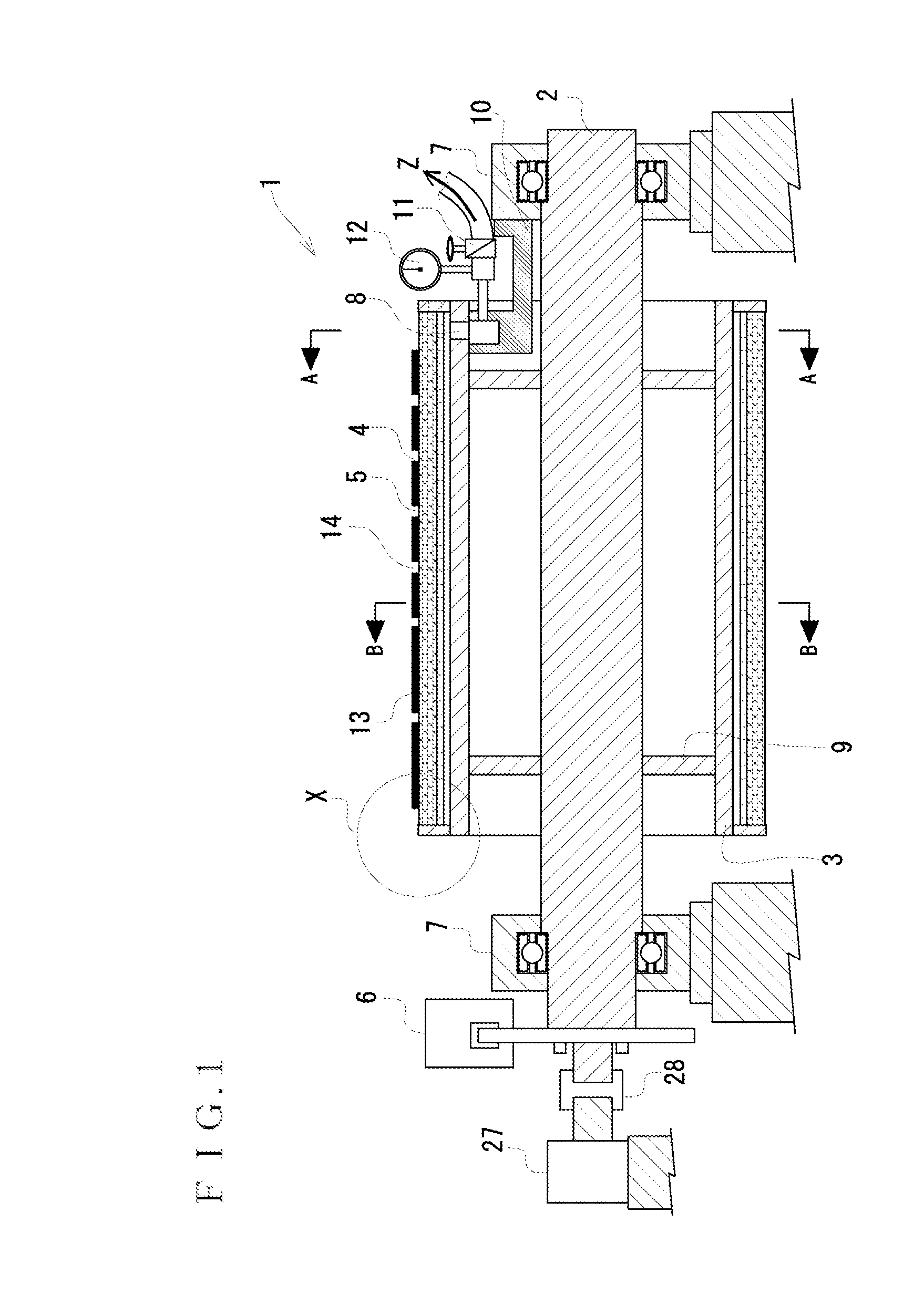
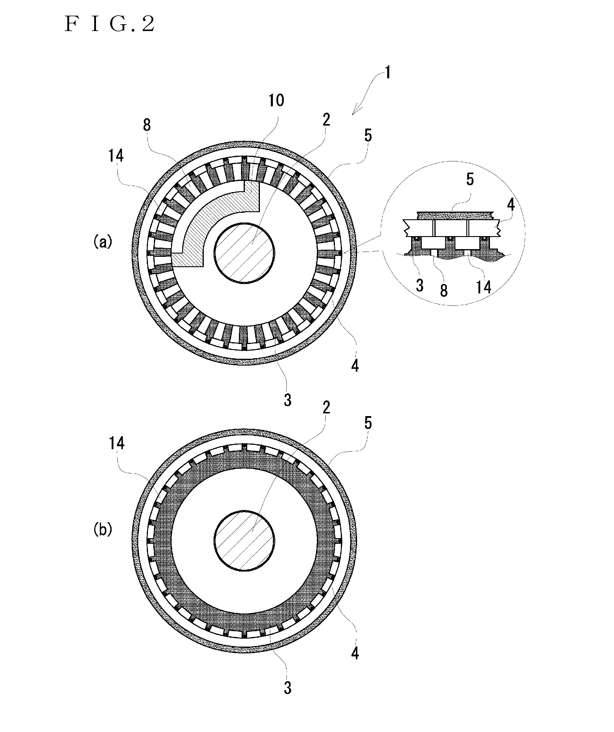
[0085]FIG. 1 is a schematic diagram which shows one example of the suction roll device to which the present invention has been applied. FIG. 2(a) is a cross sectional view taken along the line A-A, and FIG. 2(b) is a cross sectional view taken along the line B-B in the schematic diagram of FIG. 1. FIG. 3(a) is a schematic cross sectional view which shows a position corresponding to another example of a negative pressure conduction portion of the suction roll device, and FIG. 3(b) is a schematic cross sectional view which shows a position corresponding to still another example of the negative pressure conduction portion of the suction roll device. FIG. 4(a) is a schematic diagram which shows an internal cylinder, FIG. 4(b) is a schematic diagram which shows an intermediate cylinder, and FIG. 4(c) is a schematic diagra...


PUM


Abstract

The negative pressure roll 1 is provided with a rotating shaft 2, an internal cylinder 3, an intermediate cylinder 4 and a multi-layered non-woven fabric laminated outer layer 5. Further, the rotating shaft 2 is a member at the center of rotation of the negative pressure roll 1 and connected to the internal cylinder 3 by a reinforcement circular disk 9. Still further, the internal cylinder 3 is formed in a tubular shape and rotates together with the rotating shaft 2. In addition, the rotating shaft 2 and the internal cylinder 3 correspond to a rotating main body. Further, the intermediate cylinder 4 is a cylindrical tubular material formed outside the internal cylinder 3 and rotates in association with the rotating shaft 2 and the internal cylinder 3. Still further, the multi-layered non-woven fabric laminated outer layer 5 is formed outside the intermediate cylinder 4 and given as a part at which the negative pressure roll 1 is in contact with the metal strip 13. The multi-layered non-woven fabric laminated outer layer 5 also rotates in association with the rotating shaft 2, the internal cylinder 3 and the intermediate cylinder 4. In addition, the negative pressure roll 1 is provided with a controller 6 for suppressing rotation of the negative pressure roll 1.

Description

CROSS REFERENCE TO RELATED APPLICATIONS[0001]This patent application is a U.S. national stage application under 35 U.S.C. §371 of International Patent Application No. PCT / JP2013 / 052742 filed on Feb. 6, 2013, the disclosure of which is hereby incorporated by reference in its entirety. The International Application was published in Japanese on Aug. 14, 2014, as International Publication No. WO 2014 / 122737 A1 under PCT Article 21(2).TECHNICAL FIELD[0002]The present invention relates to a suction roll device. More specifically, the present invention relates to a suction roll device which is capable of firmly gripping and conveying or controlling a variety of long materials without damaging them and also capable of reliably winding them.BACKGROUND ART[0003]There exist long materials which can be cut and processed depending on a product to be used and an object. These long materials include metal strips having a predetermined thickness and sheet-like products formed with paper, resin and ...

Claims


Application Information

Patent Timeline
Patent Type & Authority Applications(United States)
IPC IPC(8): B65H27/00B65H23/14B65H20/12
CPCB65H27/00B65H20/12B65H23/14B65H2701/173B65H2403/7255B65H2406/332B65H2401/14B65H2401/242B65H2404/531B65H2406/331B65H23/245B65H2406/33B65H2401/20
Inventor HASHIKAWA, YOSHITOIKEDA, RYOUTA
Owner JDC INC
Why Eureka
Try Eureka