Paper feeder and image forming apparatus

a technology of image forming apparatus and feeder, which is applied in the direction of thin material processing, instruments, and article separation, can solve the problems of inability to implement a one-touch action to move the locking pin upward and downward, and achieve the effect of restricting the wobbling of the width regulating member

Active Publication Date: 2015-04-16
KONICA MINOLTA INC
View PDF5 Cites 14 Cited by
  • Summary
  • Abstract
  • Description
  • Claims
  • Application Information

AI Technical Summary

Benefits of technology

[0010]According to one aspect of the present disclosure, a paper feeder includes a recording-media container, a width regulating member, and a locking mechanism. The recording-media container is attachable to and detachable from a body of an image forming apparatus. The recording-media container is configured to store a recording medium. The width regulating member is configured to regulate a position in a widthwise direction of the recording medium stored in the recording-media container. The locking mechanism is configured to steplessly change a movable range of the width regulating member in the widthwise direction. The width regulating member includes a lever configured to cooperate with the width regulating member to hold the locking mechanism so as to bring the locking mechanism into an unlocked state. The locking mechanism in a locked state is configured to restrict movement of the width regulating member in the widthwise direction, and configured to restrict wobbling of the width regulating member in a direction orthogonal to the widthwise direction.

Problems solved by technology

Thus, in the series of actions, it has been impossible to implement a one-touch action to move the locking pin upward and downward while moving the side regulating plates in the widthwise direction.

Method used


Image

  • Paper feeder and image forming apparatus
  • Paper feeder and image forming apparatus
  • Paper feeder and image forming apparatus

Examples


Embodiment Construction

[0022]The embodiments will now be described with reference to the accompanying drawings, wherein like reference numerals designate corresponding or identical elements throughout the various drawings.

[0023]In the following description, terms (for example, “left and right” and “upper and lower”) indicating specific directions and positions are used where necessary. In this respect, the direction perpendicular to the paper plane of FIG. 3 is defined as front view. The terms are used for the sake of description and not intended to limit the technical scope of the present invention.

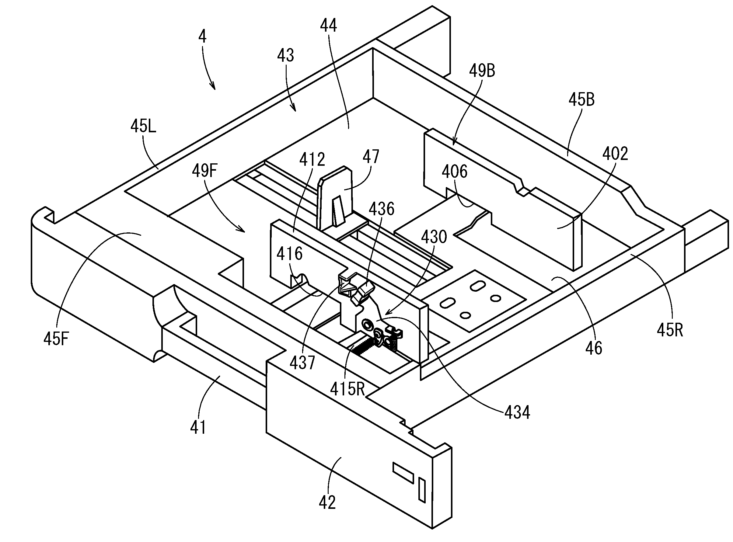
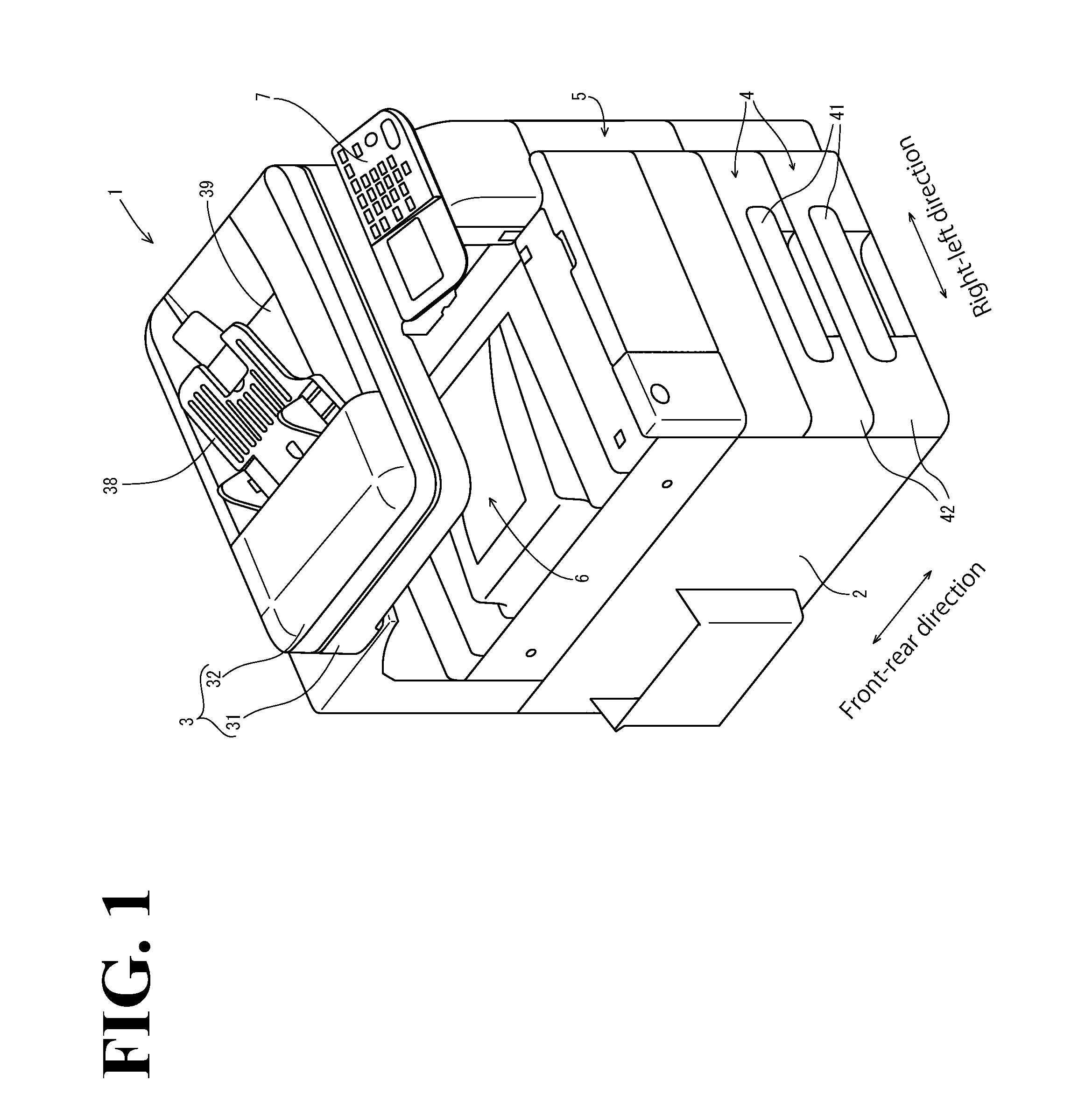
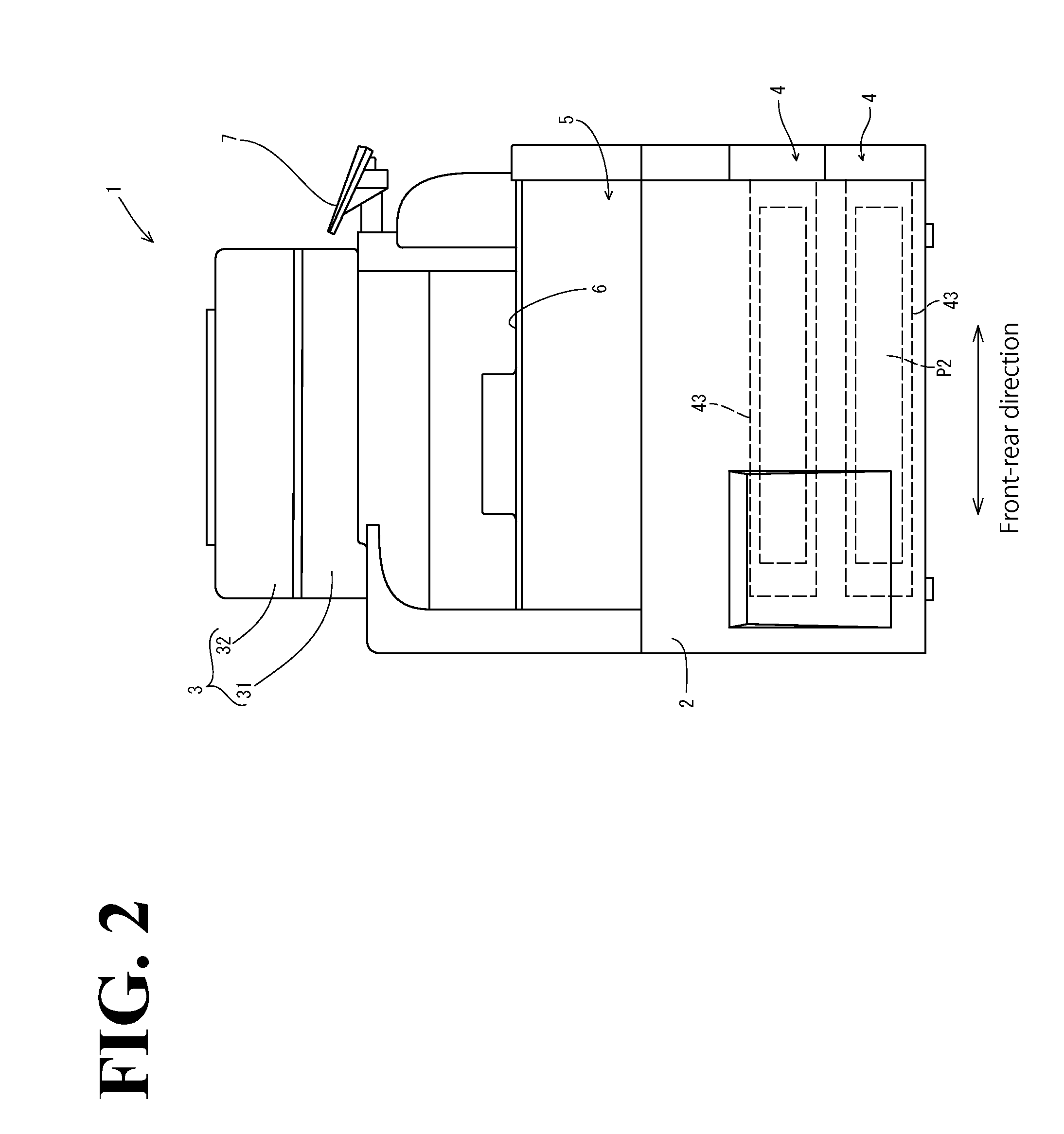
[0024]A general arrangement of the image forming apparatus common to the following individual embodiments will be described below with reference to the drawings. As shown in FIGS. 1 and 2, an image forming apparatus 1 includes an image reader 3, a paper feeder 4, an image forming device 5, a paper discharge tray 6, and an operation panel 7. The image reader 3 reads an image from an original P1. The paper feede...


PUM


Abstract

A paper feeder includes a recording-media container, a width regulating member, and a locking mechanism. The recording-media container is attachable to and detachable from a body of an image forming apparatus. The recording-media container stores a recording medium. The width regulating member regulates a position in a widthwise direction of the recording medium stored in the recording-media container. The locking mechanism steplessly changes a movable range of the width regulating member in the widthwise direction. The width regulating member includes a lever configured to cooperate with the width regulating member to hold the locking mechanism so as to bring the locking mechanism into an unlocked state. The locking mechanism in a locked state restricts movement of the width regulating member in the widthwise direction, and regulates wobbling of the width regulating member in a direction orthogonal to the widthwise direction.

Description

CROSS-REFERENCE TO RELATED APPLICATIONS[0001]The present application claims priority under 35 U.S.C. §119 to Japanese Patent Application No. 2013-214536, filed Oct. 15, 2013. The contents of this application are incorporated herein by reference in their entirety.BACKGROUND OF THE INVENTION[0002]1. Field of the Invention[0003]The present invention relates to a paper feeder and an image forming apparatus.[0004]2. Discussion of the Background[0005]As conventionally known, image forming apparatuses include a paper feeder. The paper feeder loads recording media for image formation and stores the recording media. The paper feeder is capable of being put into and taken out from the body of the image forming apparatus in order to replenish and store recording media. The paper feeder includes a recording-media container and a width regulating member. The recording-media container houses recording media. The width regulating member regulates the width position of the recording media stored in...

Claims


Application Information

Patent Timeline
Patent Type & Authority Applications(United States)
IPC IPC(8): B65H1/04B65H9/10G03G15/00
CPCB65H1/04G03G15/6529B65H9/101B65H1/266B65H2403/41B65H2403/531B65H2405/114B65H2405/121B65H2511/12B65H2511/22G03G15/6502G03G2215/00713G03G2221/1654B65H2402/54B65H2220/01B65H2220/04
Inventor DOSHIDA, YUKI
Owner KONICA MINOLTA INC
Why Eureka
Try Eureka